Continue to Site

Welcome to our site!

Electro Tech is an online community (with over 170,000 members) who enjoy talking about and building electronic circuits, projects and gadgets. To participate you need to register. Registration is free. Click here to register now.

  • Welcome to our site! Electro Tech is an online community (with over 170,000 members) who enjoy talking about and building electronic circuits, projects and gadgets. To participate you need to register. Registration is free. Click here to register now.

Op-Amps at high frequencies

Status
Not open for further replies.

YAN-1

New Member
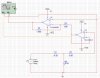
Hello everyone. I am trying to simulate a certain circuit on multisim but I'm getting some weird results. To make a long story short, I have a siusoidal signal of 0.9V amplitude and I need to amplify it to a sine wave oscillating between -5V and 5V so that I can then clip the negative part and obtian a signal that is basically representing zeros and ones. The signal is at 315 MHz and I think this is causing trouble.

I first acquire the signal through a unity-gain op-amp buffering stage and then try to amplify it using a second stage. However, the op-amp stages are not functioning as they are supposed to! The first stage is alright but the second one does not amplify at all. Instead, it attenuates the signal and shifts it. If I increase the resistor ratio even more, it shifts the signal by a dc value. However, when I reduce the signal's frequency to about 1MHz, the op-amps function normally, even though the second one doesn't amplify like it's supposed to. This op-amp is supposed to be a high-frequency amplifier. Is there an effect on the operation of op-amps when high freqencies are used? Your help and insight would be much appreciated. Thanks a lot.

Nichola V. Abdo
 

Attachments

  • Op-Amp CCT.JPG
    Op-Amp CCT.JPG
    131.6 KB · Views: 420
YAN-1 said:
Is there an effect on the operation of op-amps when high freqencies are used?

yes, of course. The properties of any op amp are frequency dependent.
You can't use the ha2540 op amp as a voltage follower. The voltage gain must be equal to 10 (min.)
 
Last edited:
Nigel Goodwin said:
Opamps are basically for audio, for RF use and particularly UHF use, you need an RF amplifier - NOT an audio one.

Nigel, although what you are saying is generally true, I think he is attributing the use of 300+ MHz to the fact that the CLC449 has a bandwidth of 1200 MHz according to the datasheet (see below).

Now I have no idea if the simulation program has the correct parameters for such an operational amplifier and simulates it properly. At those frequencies, I wouldn't trust the simulator - I would probably go ahead and build a test circuit. Building such high frequency circuits is difficult! You'd probably want to do it with surface mount etc. etc. It usually takes an experienced person to prototype such circuits - but may be worth a shot.

General Description
The Comlinear CLC449 is an ultra-high-speed monolithic op
amp, with a typical -3dB bandwidth of 1.2GHz at a gain of +2.
This wideband op amp supports rise and fall times less than 1ns,
settling time of 6ns (to 0.2%) and slew rate of 2500V/µs. The
CLC449 achieves 2nd harmonic distortion of -68dBc at 5MHz
at a low supply current of only 12mA. These performance
advantages have been achieved through improvements in
Comlinear’s proven current feedback topology combined with a
high-speed complementary bipolar process.
The DC to 1.2GHz bandwidth of the CLC449 is suitable for many IF
and RF applications as a versatile op amp building block for replace-
ment of AC coupled discrete designs. Operational amplifier
functions such as active filters, gain blocks, differentiation, addition,
subtraction and other signal conditioning functions take full
advantage of the CLC449’s unity-gain stable closed-loop
performance.
 
Analog said:
Now I have no idea if the simulation program has the correct parameters for such an operational amplifier and simulates it properly. At those frequencies, I wouldn't trust the simulator - I would probably go ahead and build a test circuit. Building such high frequency circuits is difficult! You'd probably want to do it with surface mount etc. etc. It usually takes an experienced person to prototype such circuits - but may be worth a shot.

I agree.. the simulator can have correct parameters for those op amp, but - as Analog wrote - you can't trust the results. The layout is an important aspect of the project, do you agree?
What about those resistors? Do you expect that they behave like at low frequencies?
 
Last edited:
Analog said:
Nigel, although what you are saying is generally true, I think he is attributing the use of 300+ MHz to the fact that the CLC449 has a bandwidth of 1200 MHz according to the datasheet (see below).

For RF use it's best to use RF design techniques, and as you say, layout will be very critical at these frequencies - I doubt a simulator will have anything worthwhile to contribute?.
 
What logic levels do you need, and what logic family (or device) do you plan to apply this signal to?
 
Thanks a lot people. Well the output of the amplifying stage will be inputted (after clipping the negative part) into a prescaler and then to a phase detector as part of a PLL circuit. The AC signal, in fact, represents the output of a VCO. My professor said that he has been using the AD811 op-amp and similar fast op-amps for such rf circuits successfully for a long time and that he too thinks that the problem is probably with the simulating program rather than the principle itself.
 
YAN-1 said:
Thanks a lot people. Well the output of the amplifying stage will be inputted (after clipping the negative part) into a prescaler and then to a phase detector as part of a PLL circuit. The AC signal, in fact, represents the output of a VCO. My professor said that he has been using the AD811 op-amp and similar fast op-amps for such rf circuits successfully for a long time and that he too thinks that the problem is probably with the simulating program rather than the principle itself.
Interesting, but you didn't answer my questions. Do you have a PLL that will run on 5V at 300+MHz, or are you after some other logic level? I'm not just asking out of curiosity. Knowing the details of your application can help us give you useful answers.
Note that the gain of the CLC449 is down about 8dB at 300MHz, which means that you'll have a net gain of 12dB, which is a gain of 4 (not including the loss of your "voltage follower"). Not too effective. Furthermore, the peak output voltage is only 3.1V. Also, the slew rate is 2000V/usec. This means you can only get 2V p-p output at 319MHz. You plan to clip the negative portion. Is 1V peak enough?

for a sine wave, max dv/dt=Aw, where w=2*pi*f, A=peak sine wave voltage
A=(dv/dt)/w
A=2e9/(2*pi*319e6)
A~1

A sine wave should be fine to apply to a PLL, even a digital one, at 319MHz. You just need the correct gain and DC offset (with AC coupling), and maybe some Schottky limiters for protection if your source amplitude is variable. I would not try to get that gain with op amps.
 
Ron H said:
I would not try to get that gain with op amps.

Likewise! - frequency synthesisers have been about for MANY years now, I've never seen a UHF one use an opamp as an amplifier - this may be for cost reasons?, but I suspect it's because it's a pretty poor choice of component?.
 
Why not go for a simpler option like a common emitter amplifier followed by an emitter follower?

Op-amps seem more trouble than they're worth for this application.
 
Ron H said:
Interesting, but you didn't answer my questions. Do you have a PLL that will run on 5V at 300+MHz, or are you after some other logic level? I'm not just asking out of curiosity. Knowing the details of your application can help us give you useful answers.
Note that the gain of the CLC449 is down about 8dB at 300MHz, which means that you'll have a net gain of 12dB, which is a gain of 4 (not including the loss of your "voltage follower"). Not too effective. Furthermore, the peak output voltage is only 3.1V. Also, the slew rate is 2000V/usec. This means you can only get 2V p-p output at 319MHz. You plan to clip the negative portion. Is 1V peak enough?

for a sine wave, max dv/dt=Aw, where w=2*pi*f, A=peak sine wave voltage
A=(dv/dt)/w
A=2e9/(2*pi*319e6)
A~1

A sine wave should be fine to apply to a PLL, even a digital one, at 319MHz. You just need the correct gain and DC offset (with AC coupling), and maybe some Schottky limiters for protection if your source amplitude is variable. I would not try to get that gain with op amps.

Well I'm not sure how to do these calculations. The signal I have is a sine wave at 315 MHz and with a peak of 0.9V. It is the output of a VCO. I want to transform it such that the high is given by 5V and the negative is given by 0V. This signal will then be inputted into a 1:64 prescaler to get a signal of 4.9218 MHz. This signal then feeds the MC145151-2 PLL IC as the feedback signal from the VCO. The IC is set at a 1:1008 prescaler so that the signal's frequency is further reduced to 4882 Hz. It is then compared with the 5MHz crystal (prescaled by 1:1024) so that the entire system locks at 315 MHz at the output of the VCO.

Now my problem is in the stage between the VCO and the prescaler. The VCO outputs a 0.9V peak sine wave and the prescaler accepts TTL ones and zeros. What do you think I should do? Thanks a lot.

Nichola
 
YAN-1 said:
Now my problem is in the stage between the VCO and the prescaler. The VCO outputs a 0.9V peak sine wave and the prescaler accepts TTL ones and zeros. What do you think I should do? Thanks a lot.

Check the amplifers used in frequency counters, these do almost exactly the same job. Generally they use either a single FET or transistor, or perhaps two.

Bear in mind you DON'T need a 5V p-p signal, just one that meets the TTL input specifications.

BTW - have you actually tried feeding the VCO directly into the prescaler?.
 
The prescaler is MB506.

Well I haven't tried connecting the VCO directly to the prescaler. The thing is I am supposed to design the circuit first and then get the components and test it. Someone suggested 'thresholders' for me as means of converting the signal to zeros and ones. In the mean time, I'm reading something related to the use of high-speed op-amps in rf circuits. Don't know if that would do any good but we'll see!
 
YAN-1 said:
The prescaler is MB506.

Well I haven't tried connecting the VCO directly to the prescaler. The thing is I am supposed to design the circuit first and then get the components and test it. Someone suggested 'thresholders' for me as means of converting the signal to zeros and ones. In the mean time, I'm reading something related to the use of high-speed op-amps in rf circuits. Don't know if that would do any good but we'll see!
You either have not looked at the MB506 datasheet, or you don't understand it. You appear to be in way over your head here.
The input amplitude spec is -16dBm to 5.5dBm. This translates to 100mV p-p to 1.2V p-p.
The part also does not have "TTL" output levels. The output is 1.6V p-p typical, 1V p-p minimum (ECL compatible).
 
Well! Is there a chance you could just disregard my stupidity and not carefully reading the datasheets? :D

Well according to this, the VCO can directly feed the prescaler, right?
But I'm not sure if the 1.6Vp-p output signal from the prescaler is enough as an input to the MC145151-2 PLL IC. I'm not sure whether the Fin voltage level is the 500mVp-p (4th row of the table in page 13 of the datasheet) or the 0V and 5V for low and high in the rows after that. Please take a look at the datasheet.

Thanks a lot.
Nichola
 

Attachments

  • MC145151-2.pdf
    586.3 KB · Views: 240
YAN-1 said:
Well! Is there a chance you could just disregard my stupidity and not carefully reading the datasheets? :D

Well according to this, the VCO can directly feed the prescaler, right?
But I'm not sure if the 1.6Vp-p output signal from the prescaler is enough as an input to the MC145151-2 PLL IC. I'm not sure whether the Fin voltage level is the 500mVp-p (4th row of the table in page 13 of the datasheet) or the 0V and 5V for low and high in the rows after that. Please take a look at the datasheet.

Thanks a lot.
Nichola
It's the 500mV spec. AC couple the prescaler into the PLL chip.
Why are you going to so much trouble to get exactly 63 times your 5MHz reference? Why don't you just divide the VCO by 63, feed that output into one input of a phase detector, feed the 5MHz into the other input, filter and amplify the phase detector output, and feed that to the VCO control port?
There must be PLL chips out there that can do that easier than the way you are trying to do it, and a divide-by-63 prescaler should not be too hard to find.
 
Ron H said:
It's the 500mV spec. AC couple the prescaler into the PLL chip.
Why are you going to so much trouble to get exactly 63 times your 5MHz reference? Why don't you just divide the VCO by 63, feed that output into one input of a phase detector, feed the 5MHz into the other input, filter and amplify the phase detector output, and feed that to the VCO control port?
There must be PLL chips out there that can do that easier than the way you are trying to do it, and a divide-by-63 prescaler should not be too hard to find.

Sorry for not replying any sooner. Well That's basically what I'm doing but the thing is the least prescaler value for the 5MHz input for this PLL IC is 8 so I am basically doing what you're suggesting but my prescaler values are different.

One more thing..You mentioned (and it says in the datasheet) that the prescaler has an ECL output. I checked it out and it turns out it represents zeros and ones by negative voltages? So if I pass that output through a capacitor, I'll just get the normal sine wave (without the negative DC shift) and that would be suitable as an input for the PLL IC, right?
 
Status
Not open for further replies.

Latest threads

New Articles From Microcontroller Tips

Back
Top