Continue to Site

Welcome to our site!

Electro Tech is an online community (with over 170,000 members) who enjoy talking about and building electronic circuits, projects and gadgets. To participate you need to register. Registration is free. Click here to register now.

  • Welcome to our site! Electro Tech is an online community (with over 170,000 members) who enjoy talking about and building electronic circuits, projects and gadgets. To participate you need to register. Registration is free. Click here to register now.

Op Amp output noise Problem

Status
Not open for further replies.

Lighty

New Member
Hi

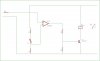
Busy building a pH controller, the "monitor" side of think works fine and its reading pH connectly, it has a output of 1V per Ph. I've taken the that voltage through a 10K resister to the input of the "switching opamp" (LM358), which it acts as a comparator against a reference voltage, the output from this drives a 2N2222 transistor which in turn drives a relay.

THE PROBLEM

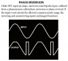
Because the input signal changes very slowly, when its at the threshold point of the opamp (against the Ref Voltage) it start to form a "square Wave" output and causing the relay to "vibrate", and not acting as a "clean" switch.

Attched is a basic schematic of the comparator and relay driver.

Thanks in advance.
 

Attachments

  • ph.jpg
    ph.jpg
    16.8 KB · Views: 433
The lousy old LM358 is very noisy. When the input voltage is near the threshold voltage then it amplifies its own noise then the output becomes unstable.
Adding positive feedback to give it a snap action is called hysteresis.
 
For this purpose an LM358 would be fine, Audioguru just hates old opamps :D

You might consider any of the (still pretty old, but far better spec) TL07x/08x series.
 
I've got a T061 and 741 (HA17741), what the difference between the TL07x/8x and the TL06x? sorry for the stupid Q
 
what the difference between say the TL061 and the TL071? Newer technology in the TL071? are they interchangeable parts?

And should I not just use a LM311, as it can drive the relay directly too?
 
ok, played around by putting a VR on the circiut to test the "feedback / hysteresis" and say the results, it "bumped" up the voltage on the switch over causing it to happen quickly - Am I right by saying that?

BUT, my display circuit reads the voltage before R4 (10k) to diplay the pH, now when the hysteresis "kicks" in it increases this voltage to, how can I stop this? by adding a diode between the display circiut connection and R4?
 
The TL06x is low power so it is slow (max output frequency is 20kHz) and has a low internal gain (typically only 6000). It is noisy (40). Its input offset voltage is high.

A TL07x has a max output frequency of 100kHz, a typical internal gain of 200,000 and a noise number of 18.

A lousy old LM358 is a dual low power opamp with a max output frequency of about 1kHz, a typical internal gain of 100,000 (but a graph shows 1 million) and a noise that is not spec'd but might be 50.
 
Last edited:
Ok, so the TL061 not the best, But i've used it on my pH circuit, should I rather change them to the TL071 or TL081? and could I just swop them? It seems to be ok so far, but mybe contrabuting to the "noise" going to the camparator?

Attached is the schematic of the circuit so far (exc. Transistor and output relay)
 

Attachments

  • pic1.jpg
    pic1.jpg
    65.6 KB · Views: 406
A TL071 has "normal" supply current, gain and bandwidth.
It is Low noise ones selected from TL081 opamps.
Unplug the TL061 and plug in a TL071.
 
since this the one opamp is a buffer between the pH probe and the rest of the circuit and requires as low as possible bias current, would the TL081 not be better suited at 30pA, same as the TL061. The TL071 has a 65pA bias.
 
hi

Just realised something, the LM358 is a single voltage supply, the others are dual voltage, now instead of switching between Gnd and Vcc+, it will switch between Vcc- and Vcc+, can I just ground the Vcc- of the TL081?
 
The MC3317x line of opamps has the same low supply current and 3V minimum supply voltage as the lousy old LM324 quad and LM358 dual opamps. The MC3317x opamps also have inputs that work when their voltage is at the minus supply voltage that could be 0V when the supply is only a positive voltage.
But the LM3xx opamps have a very low bandwidth and have crossover distortion.
The MCxxx opamps have a bandwidth to 35kHz and no crossover distortion.

The MC3407x line of opamps have normal supply current but have a bandwidth to 100kHz. They also have a minimum supply of 3V and have inputs that work at the negative supply voltage that could be 0V when the supply is only a positive voltage.

The TL07x and TL08x opamps have the Phase Inversion problem. When an input voltage gets within 4V of the negative supply voltage (which might be 0V) then the output voltage suddenly goes high.

Any opamp works from a single supply voltage if its input is biased at half the supply voltage.
 

Attachments

  • opamp phase inversion.PNG
    opamp phase inversion.PNG
    15.3 KB · Views: 286
Thanks Audioguru.

But i'm getting myself a bit confused here.

Please see attached schematic.

What I'm trying to do is:

When input from ch1 is high, output on the last opamp is high, when input low, output low - Easy, But

the about statment is only true (works) when input from ch2 is High (or low - can change to non invert input ch2 TL081), when low, it "deactivates" the function of Ch1.

hope this makes sense.
 

Attachments

  • interface.jpg
    interface.jpg
    66.3 KB · Views: 340
Why are you using opamps instead of logic gates?
Two of the opamps have positive feedback so they will not do anything.

Why does the circuit use so many offset voltage pots?
 

Attachments

  • opamp circuit.PNG
    opamp circuit.PNG
    29.2 KB · Views: 557
Why are you using opamps instead of logic gates?
Two of the opamps have positive feedback so they will not do anything.

Why does the circuit use so many offset voltage pots?

Coz I've never used Logic gate:confused:

The positive feedback if for the hysteresis, the other resistors and pot is for setting he threshold as the opamp acts as a switch.

This is for a pH probe, 1st amp is for gain, 2nd for offset (these for calibration of the probe), 3rd for switching action against the "set" pH ( this is set using R17 - R4 - R18 )

Maybe someone could steer me in the right direction with the logic gates.:eek:
 
Status
Not open for further replies.

Latest threads

Back
Top