wuchy143
Member
Hello,
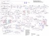
If you look at the attached schematic you will see an op-amp (U1A) in the bottom middle of the page. This is the area of concern. I'm trying to debug the issue with this PCB and I've landed to this amplifier. There are a couple issues:
1. I don't understand the op amp configuration. It looks like an integrator due to the cap in the feedback network but I'm not really sure because it doesn't function like one. I thought integrators operate such that depending on how long a voltage is at the input the amplifier increase or decrease its output(depending on polarity). When i look at the input terminals with a scope neither of these voltages vary at all. They both sit at 3V. Though, the output swings from 0V up to 4V.
2. The output when at 4V oscillates peak to peak by about 3/4V!!! Why is this? It should be a clean 4V.
Attachments
Last edited:

