Fluffyboii
Active Member
Today I had an idea. I wanted to have a Low frequency Oscillator with lm13700. Music From Outer Space has circuit diagram of one that has sinus wave output. But I know there are Voltage Controlled Low Frequency Oscillators with the same IC. The bottom diagram is voltage controlled but it lacks sinus output.

This circuit uses one of the LM13700's OTAs for LFO and another for Voltage Controlled Amplifier. But I don't want to have VCA for now so I did not build the right section of the circuit in the image and connected the triangle output of it to Music From Outer Space's LFO's triangle to sinus converter section that uses the second OTA. At the end I combined those two circuits to have a VCLFO that also has sine wave with square and triangle. My problem is that this thing doesn't want to oscillate. When I touch the pin 1 of LM13700 with my multimeter prop or tweezers I can see that a signal is created on sine output. And when I touch the other input of the lm13700 (trig out) there are similar signals being generated on sinus out accordingly. I can also see that these small voltage spikes are actually being distorted into a somewhat sinus wave with my oscillator. Triangle and square outputs also get spikes but no continuous waves are appearing. I checked and messed with pots and such and couldn't get it going.
I forgot to mention that I buffered the triangle and square outputs with tl074's other two op amps. I used tl074 instead of tl072 for specially buffering those because I know that oscillation won't happen if outputs get loaded even a tiny bit from my past experiences. Triangle is buffered like this:

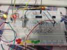
I can't really spot a problem after all. I will check it tomorrow since I am very tired today. I add the images of the circuit I made but it is very tightly soldered (bad habit of mine) so I am not expecting anyone to spot a problem on it. I know someone will ask so: All of the ICs are original, I am not naive enough to trust Chinese ICs. I first test with original ones then see if the ones I got from China works or not and then put them in if I want to preserve guaranteed original ICs.


This circuit uses one of the LM13700's OTAs for LFO and another for Voltage Controlled Amplifier. But I don't want to have VCA for now so I did not build the right section of the circuit in the image and connected the triangle output of it to Music From Outer Space's LFO's triangle to sinus converter section that uses the second OTA. At the end I combined those two circuits to have a VCLFO that also has sine wave with square and triangle. My problem is that this thing doesn't want to oscillate. When I touch the pin 1 of LM13700 with my multimeter prop or tweezers I can see that a signal is created on sine output. And when I touch the other input of the lm13700 (trig out) there are similar signals being generated on sinus out accordingly. I can also see that these small voltage spikes are actually being distorted into a somewhat sinus wave with my oscillator. Triangle and square outputs also get spikes but no continuous waves are appearing. I checked and messed with pots and such and couldn't get it going.
I forgot to mention that I buffered the triangle and square outputs with tl074's other two op amps. I used tl074 instead of tl072 for specially buffering those because I know that oscillation won't happen if outputs get loaded even a tiny bit from my past experiences. Triangle is buffered like this:
I can't really spot a problem after all. I will check it tomorrow since I am very tired today. I add the images of the circuit I made but it is very tightly soldered (bad habit of mine) so I am not expecting anyone to spot a problem on it. I know someone will ask so: All of the ICs are original, I am not naive enough to trust Chinese ICs. I first test with original ones then see if the ones I got from China works or not and then put them in if I want to preserve guaranteed original ICs.


