Continue to Site

Welcome to our site!

Electro Tech is an online community (with over 170,000 members) who enjoy talking about and building electronic circuits, projects and gadgets. To participate you need to register. Registration is free. Click here to register now.

  • Welcome to our site! Electro Tech is an online community (with over 170,000 members) who enjoy talking about and building electronic circuits, projects and gadgets. To participate you need to register. Registration is free. Click here to register now.

Op-Amp Comparator

Status
Not open for further replies.

JackJTR

New Member
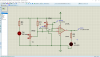
This is my first time doing a project related to Op-Amp comparator. For what i learn from all the books and online tutorial, when the Non-inverting voltage is higher than inverting voltage, the output of the OP-amp will be the +sat voltage(In this case 5V) while when the Inverting voltage is higher than the Non-inverting voltage , the output voltage will be -sat voltage( In this case 0V). But what i get from the simulation is that when the Non-Inverting Voltage is higher than the inverting voltage, the output voltage of the op-amp is almost 0 while when the inverting voltage is higher than the non-inverting voltage, the output voltage is even smaller and closer to 0V. Anyone know what happen or what should i do so that when the Non-inverting voltage is higher than the inverting voltage , the output voltage will be 5V and the LED will light up?

Thanks in advance!
 

Attachments

  • Screenshot (106).png
    Screenshot (106).png
    101.5 KB · Views: 172
The output of the LM393 is an open collector.
Look at the datasheet:

The LM393 is not an op-amp it is a comparator, there is a difference.

To make it all work, connect it up like this:
Modified LM393.png


Please excuse the scrappy sketch.

JimB
 
Status
Not open for further replies.

New Articles From Microcontroller Tips

Back
Top