Continue to Site

Welcome to our site!

Electro Tech is an online community (with over 170,000 members) who enjoy talking about and building electronic circuits, projects and gadgets. To participate you need to register. Registration is free. Click here to register now.

  • Welcome to our site! Electro Tech is an online community (with over 170,000 members) who enjoy talking about and building electronic circuits, projects and gadgets. To participate you need to register. Registration is free. Click here to register now.

op amp comparator circuit

Status
Not open for further replies.
Not quite, two diodes reversed bias with pullup will make And gate. :)

Hi Mike,


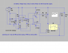
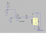
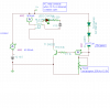
Well Mike, that's your version. Mine uses three :)

I was going to use a third diode just to make sure the
transistor turns off fully. With two diodes and pullup, there could
still be as much as 0.6v at the base of the transistor. With an
extra diode in series with the transistor base and a light pulldown
on the base, the transistor base sees about 0.15v and turns off
fully. Depending on load it may work anyway, but it could be close
without the extra diode, not something i would be comfortable with.
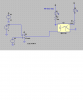
Another version would put the extra diode in series with the emitter
if power considerations allow.
Still yet another version could use an extra resistor to divide the
diode voltage down so the base sees about 1/2 a diode drop instead
of the whole diode drop.

That reply was a little joking too BTW :)
 
Last edited:
R6 and R7 is supposed to be a pot

hav'nt figured out how to use a pot (variastor) in spice.
and how do you get the triangle wave??
the monitor is supposed to be adjusted to close relay at around 10-11 volts
I played with it in spice as well as Tina (Tina dosn't have an op amp with single supply) but it still worked.
still trying to figure out all the little things in spice = multi planes, varistors, steeping through the battery voltages(change from 12 to 11 to 10 etc. to see the circuit in operation.
we is learning
will look at your sims and decipher. what did you change??
 
hav'nt figured out how to use a pot (variastor) in spice.
Why not use the 'voltage' model and set the V range to suit
and how do you get the triangle wave??

Use the PWL piece wise list
You can see that list I entered,modify it to suit your app


the monitor is supposed to be adjusted to close relay at around 10-11 volts
I played with it in spice as well as Tina (Tina dosn't have an op amp with single supply) but it still worked.
still trying to figure out all the little things in spice = multi planes, varistors, steeping through the battery voltages(change from 12 to 11 to 10 etc. to see the circuit in operation.
we is learning
will look at your sims and decipher. what did you change??

hi,
If you have a query, please ask, post your asc file so that we can edit it and post it back, OK.?

**broken link removed**
 
Last edited:
will try out the voltage model. need to locate first = lol

On the schematic part press F2 key then select 'voltage'
 

Attachments

  • AAesp05.gif
    AAesp05.gif
    10.5 KB · Views: 419
I tried everything but!!

couldn't get the relay to open using a PNP transistor
resorting to opticolupter
looks like it works??
 

Attachments

  • batt mont.PNG
    batt mont.PNG
    42.7 KB · Views: 213
now I is in mud

trying to sim a simple relay being controlled by an op amp
got the LEDs to work but tried inserting a pnp transistor - nada
I figure the LED works so insert an opticoupler
still isn't right??
Getting really lost in Idaho
something so simple and run into a snow storm
 

Attachments

  • opamp sim.PNG
    opamp sim.PNG
    21.4 KB · Views: 345
  • op sim1.asc
    1.3 KB · Views: 137
trying to sim a simple relay being controlled by an op amp
got the LEDs to work but tried inserting a pnp transistor - nada
I figure the LED works so insert an opticoupler
still isn't right??
Getting really lost in Idaho
something so simple and run into a snow storm

hi
Look at the V symbols... you have +v and v+..... they are different!!!!
 
looks like a go I think

made correctiobs as per eagle eye Eric
added couple of LEDs just to be sure I have current flowing.
 

Attachments

  • op sim 2.PNG
    op sim 2.PNG
    16.7 KB · Views: 270
circuit would keep cycling -- duh??

got to thinking that using the op amp comparator circuit it would sense whan the batteries are low then turn on the charger.
all well BUT the charger would output up to 13.5 v thus triggering the op amp circuit off
then the batteries wouldn't be fully charged but the cycle would start all over again.
got to moving parts around etc.
came up with a frankienstein circuit (its close to halloween)
tried numerious combos and this works great.
could lower the base resister as it is really low in current??
haven't tried in LT spice (the LEDs don't light up in spice.)
used Tina and works great
any comments
still woundering why a 15v zener is nly one that seemed to work?
 

Attachments

  • charger cut off.PNG
    charger cut off.PNG
    26.3 KB · Views: 481
There is yet another route that you could take in the application:
When the sun comes back out the solar panels will began to charge the battery again. The idea behind the charger would only be to keep the system functioning until the sun comes back out. What would work is to lower the voltage on the charger down to 12 volts and have the circuit maintain the battery state until the solar cells can charge the battery again. The only thing that the charger will have to maintain is a 12v 1amp pump and the 100 or so ma used by the controller. sort of like a reversed ups system. you would have to incorporate a indicator lamp to let the user know that the system is drawing power from the household. Basically to warn the user that if it's sunny out and the light is on then something is wrong with the solar panels. The main thing is the frost protection, if the battery dies and the circuit doesn't have the juice to run the pump and keep the water circulating then the pipes will burst.
 
Last edited:
One small problem

a battery charger usually outputs 13.5 volts or there about so it can charge the battery.
If 12volts were used as the output the battery wouldn't charge or not charge fully.
You need to at least 13 volts or so.
at least thats what I an lead to believe.
been wrong before..
have solution to keep charger on until fully charged instead of off on off on due to the monitor reading the battery voltage as well as the charger voltage.
 
but if you remember, i didn't want it to fully charge just charge enough to sustain the pump and circuit for enough time for the sun to come back out. This circuit would defeat the purpose of having a solar array. The idea is to get power for free and use power only when i have to. As it stands, the system that is in place now would take a week or more without sun to deplete the battery. If then after that time the charger were to kick in and fully charge the battery then if the next day the sun comes out for a week, that is a week of lost solar power. My solar array produces 14.5 @ 6amps in a 7 hour day this would charge the battery to its full state.
I'm not saying that the charger idea wouldn't work for my application just that it wouldn't help with the efficiency that i'm looking for. If it's to late in the project then i will make due. However if this could solve the issue then it will only benefit me. As for the parts, i would like to order from the electronicgoldmind that you suggested in another post. I have surfed around in there and if the shipping is quick enough then i found myself a new supplier.
 
Last edited:
you can adjust for desired voltage

the monitor will monitor the batteries and turn on the charger at what ever voltage you adjust it for.
the over charge circuit is to prevent overcharging the batteries.
If you want the solar panel to charge the batteries then have the ac charger kick in if not enough sun then yes its doable
just a change over type circuit so if the batteries go below a set level then the ac charger kicks in.
Is this correct?
 
yes if the battery get below 12 volts then the charger should kick in and maintain the voltage at 12v. When the sun comes back out the solar arrays will put 14.5 v into the battery. this is when the charger should shut down. Basically if i read you post properly, that is the problem that you are having with the charger. When the battery senses that the voltage is down to 11.5volt the charger turns on but as soon as the 13.5 volts from the charger is sensed then the circuit will shut down. So to solve the problem we would set our high and low to 11.90v = on 12.10 = off Adjust the charger to charge at 12v with 1.5 amps.
 
yes just adjust the monitor for desired voltages.
Trying to get parts list from goldmine.
found an adjustable voltage reference as well as several opticouplers.. One is a HE PhotoMos . never heard of them?? AQV250
will get back to you later.
 
Status
Not open for further replies.

Latest threads

Back
Top