I am working on an Onkyo SR606 amp which has problems with going into protection mode. I have isolated one channel due to shorts on the output transistors but it is still doing it. To make it harder it only does it intermittently, sometime can go 15 min with no issues, other times straight away. This happens with no inputs or speakers connected.
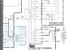
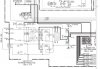
So, I am working through the schematics and have come across something I have not seen before so would like your advice. I am looking at the power supply circuit which I have attached. The voltage from the transformer between the yellow and green cables is 87 Vac and at plug J6952 is 43 Vac. Looking at the drawing both these supply’s go into bridge rectifiers and they are then connected in parallel on the output. So, I was expecting about approximately 87 Vdc on the output, but I am getting 110 Vdc on both rectifier outputs.
Am I missing something? Also, it has a ground amp which looks like it is connected to the center capacitor network on the bridge inputs. I have not seen this before and cannot find much on the net to understand what this is for. Can anyone give so advice on this part of the circuit please.
You should be able to see the service manual here
**broken link removed**