Continue to Site

Welcome to our site!

Electro Tech is an online community (with over 170,000 members) who enjoy talking about and building electronic circuits, projects and gadgets. To participate you need to register. Registration is free. Click here to register now.

  • Welcome to our site! Electro Tech is an online community (with over 170,000 members) who enjoy talking about and building electronic circuits, projects and gadgets. To participate you need to register. Registration is free. Click here to register now.

One shot latch

Status
Not open for further replies.

pdistance

New Member
Hi, I am working on a hobby project that requires a mechanical 5v dc solenoid to latch into a set position after 1 second and stay there. This solenoid circuit is triggered by the vibration of a micro engine start up so I think this will work but need advice on the circuit
1) The engine starts and the solenoid is in initial idle position
2) A positive pulse is then generated from a transducer circuit detecting this
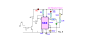
3) This switches a transistor which applies a low to pin 2 of a 555 circuit
4) After 1 second the solenoid is activated and it stays in this activated position
I have built a number of circuits but I would appreciate some advice on the following
1) How do I delay the output to the solenoid for 1 second after trigger. I can build circuits that have an immediate output after low to pin 2 of the 555 and then adjust resistor cap combos to change pulse times etc but not delay the inital switch on
2) In the circuits I have built I am also finding it difficult to stop the continuous low input to the 555 from the engine transcucer producing further triggers to the solenoid after the first 1 sec output has finished. I only want it to trigger once after 1 second so maybe SCR is the way to go but I do need to keep this small running on a miniature batttery.
 
hi,
If I follow your description, it appears you need a delay triggered by the transducer, say 1second and when the delay resets it sets a latch.

You need to AC couple the transducer signal trigger to the 555, this will avoid holding the Trig input low.

The latch could be a simple CD4093 IC latch, which would drive a suitable transistor for the solenoid coil.
Do you follow OK.?

EDIT: post your existing circuit so that we can add the changes.
 
Last edited:
Now that Ive had to think so much about writing the query, I am thinking could the initial trigger, produce a 555 high output which after one second feeds a low into a second 555 to enable solenoid....... not sure and doesnt solve the reapplication of low to first 555 after 1 second.
 
Now that Ive had to think so much about writing the query, I am thinking could the initial trigger, produce a 555 high output which after one second feeds a low into a second 555 to enable solenoid....... not sure and doesnt solve the reapplication of low to first 555 after 1 second.

hi,
Yes, but how would the second 555 hold the solenoid ON, you would still some form of latch
 
hi Eric, you are correct. I dont seem to be ablt to attach schematics but the timer circuit I modified for time = 1 sec was from here (the "10 min timer) **broken link removed**
 
hi Eric, you are correct. I dont seem to be ablt to attach schematics but the timer circuit I modified for time = 1 sec was from here (the "10 min timer) **broken link removed**

hi,
Do you mean this circuit, if yes thats a simple mono-stable but its a normally open momentary push switch that triggers the 555.
As I understand your post, the transducer is holding the pin low after the initial pulse.??

Note: the transducer/ push button actually pulls the RESET pin low
 

Attachments

  • AAesp01.gif
    AAesp01.gif
    4.3 KB · Views: 216
Last edited:
Yes Eric that is the circuit and the transducer is fed from a running engine. Once it starts I need the solenoid to activate after the one second but it needs to stay but with the pin low from the transducer as you described. I only actually need the solenoid on for 10 seconds (doesnt matter if it is more) so if I could pause the trigger for 1 sec the solenoid could be on for as long as it wants but it is a catch 22 and I am a bit bogged down with it.
 
i read the thread about adding circuits but print screen, cut and paste etc didnt seem to work. Probably really easy but could you tell me how I put up an image and I think it would be very obvious what I am trying to do. None of the link/function boxes seem to work to allow me add a pic but I may be missing something simple.
 
Yes Eric that is the circuit and the transducer is fed from a running engine. Once it starts I need the solenoid to activate after the one second but it needs to stay but with the pin low from the transducer as you described. I only actually need the solenoid on for 10 seconds (doesnt matter if it is more) so if I could pause the trigger for 1 sec the solenoid could be on for as long as it wants but it is a catch 22 and I am a bit bogged down with it.

hi,
This is an example of the AC coupling I stated, this shows a +V going pulse input of at least 2V from the transducer is required to ensure the transistor creates a RESET/TRG low going pulse.

The timing components need to be changed to give the 1sec delay.
The second mono for 10sec+, would be triggered by the first 555 at the end of the 1sec delay.
Again, choose the timing components for 10secs and AC couple the two 555.

Do you follow OK.?
 

Attachments

  • 555a.png
    555a.png
    5.1 KB · Views: 218
i read the thread about adding circuits but print screen, cut and paste etc didnt seem to work. Probably really easy but could you tell me how I put up an image and I think it would be very obvious what I am trying to do. None of the link/function boxes seem to work to allow me add a pic but I may be missing something simple.

hi,
As you are new to the Forum, the Moderators will have to check images before they are posted...
 
I must say you have been really helpful. Just to clarify as I am rusty and I should probably build it later but while you are kindly on the thread.... If I applied a steady voltage above 2v~ the 555 timer output would trigger pretty instantly and I could adjust the pin 6/7 rc network for 1 second. this would feed into a second 555 timer circuit with for example a delay of 10 seconds and the whole circuit would not retrigger as the transistor stays on from the transducer and once the initial charging above pin 2 of 555 timer one occurs ?
 
I must say you have been really helpful. Just to clarify as I am rusty and I should probably build it later but while you are kindly on the thread.... If I applied a steady voltage above 2v~ the 555 timer output would trigger pretty instantly and I could adjust the pin 6/7 rc network for 1 second. this would feed into a second 555 timer circuit with for example a delay of 10 seconds and the whole circuit would not retrigger as the transistor stays on from the transducer and once the initial charging above pin 2 of 555 timer one occurs ?

The applied voltage from the transducer should be a high going pulse or edge.

This will trigger the first 555 ON for 1sec, as the first 555 output goes low, as its AC coupled to second 555 RESET/TRG it will trigger the second 555 ON for 10 seconds.
 
Confused about one thing: the 4093 is a Schmitt trigger NAND. How is this a latch?

hi,
Use two of the four internal gates in the IC and cross connect them.

ie;
Output of #1 to to an input on #2
Output of #2 goes to input of #1

Use the two unused input pins to Set and Reset the latch... low going to set or reset... OK.?

EDIT:
Showing sp to /SET, if a low is applied to rs it will latch the into other state

BTW: it will work with a CD4011 , I prefer the 4093 for the Schmitt inputs
 

Attachments

  • AAesp02.gif
    AAesp02.gif
    32 KB · Views: 215
Last edited:
Use two of the four internal gates in the IC and cross connect them.

ie;
Output of #1 to to an input on #2
Output of #2 goes to input of #1

Use the two unused input pins to Set and Reset the latch... low going to set or reset... OK.?

OK, thanks. But you show two outputs, va & vb: how are these used? Which one would you use as the latched output?

Maybe give us a truth table to show how this works?

Also, will this work with regular (TTL) NANDs, like a 74ALS20?
 
Now that Ive had to think so much about writing the query, I am thinking could the initial trigger, produce a 555 high output which after one second feeds a low into a second 555 to enable solenoid....... not sure and doesnt solve the reapplication of low to first 555 after 1 second.

Actually it would, if you used the continuous output of the 2nd 555, configured as a bi-stable latch, to disable the 1st one.
 
Hi Brown Out, I havent played with electronics for many years so apologies for being rusty. Could you post this type of latch circuit (or modify my initial one kindly posted by Eric) that could facilitate a trigger which is continuous once it starts.
 
Status
Not open for further replies.

Latest threads

Back
Top