Continue to Site

Welcome to our site!

Electro Tech is an online community (with over 170,000 members) who enjoy talking about and building electronic circuits, projects and gadgets. To participate you need to register. Registration is free. Click here to register now.

  • Welcome to our site! Electro Tech is an online community (with over 170,000 members) who enjoy talking about and building electronic circuits, projects and gadgets. To participate you need to register. Registration is free. Click here to register now.

On/Off control of an inexpensive 315MHz TX module?

Status
Not open for further replies.

blueroomelectronics

Well-Known Member
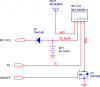
I would like to be able to power down a MO-SAWR 315MHz transmitter (same as most common 433MHz TX modules)
These little units work from 2V to 12V where the range is dependent on the supply voltage, current draw is about 15mA.
I'd also like to avoid a relay as it's a battery power thermostat it's going into, so the question is would a simple low side open drain design like the 2N7000 on the TX GND pin do the trick? Or would I need a high side driver?
Would a simple 2N2222A work as well?
Also note the 1N4148 diode, this drops the 6V battery power down to less than 5.5V for the PIC in the thermostat. I may use 3xAA for 4.5 volts and skip the diode but that's a future discussion.
 

Attachments

  • ONOFF.png
    ONOFF.png
    7.3 KB · Views: 288
Hi Bill,

you might be better off using a ZXMN3B14F (ZETEX SEMICONDUCTORS).

It has a very low RDSON of 80mΩ at VGS 4.5V and IDS=3.1A. For comparison: The 2N7000 has an RDSON of 5Ω and a pulsed IDS=1A.

The transistor is manufactured with an SOT23 package.

Hans
 
Last edited:
I would have tried a 2N2222 in series with power or ground and a 100 ohm base resistor. But the way you have it should work fine.

Have you considered putting a LDO regulator on the battery for the PIC instead of the diode?
 
Hmm, I thought about that but thought since the radio is at 6V and the PIC 5.3V I'd have to use a two transistor solution and still wind up with a voltage drop.
I could remove the diode and run the whole thing at 4.5V
Most parts will work down to 3V except the latching relay G6EK-134 (5V coil)
 
I would certainly far prefer switching the high side.

So would I. Have you considered what happens if the TX input is low when the GND terminal is floating at near the battery positive voltage? This is probably an "illegal" state for the module to be in, and may even damage it.

If you have control of the TX Pin on the PIC, you might avoid the issue by setting the TX to HiZ before turning off the rf module.
This would work if the module and the PIC had the same Vdd, but they don't!
 
Last edited:
Are you concerned with the voltage drop as the batteries drain? If so you could add a voltage boosting circuit to generate a regulated 9V or 12V from the varying battery input. It looks like that could maximize your transmission range as well.

Ooh Mike makes a good point as well. If the ground is floating but power still applied, you may end up doing strange things to the transistors in your transmitter.
 
Last edited:
Hmm, I would prefer high side driving and the range would probably only need to be ~15m
The max power is 57mA according to the datasheet I wonder if I could combine 3 PIC output pins (20mA x 3) to source the radio and run the design directly from 3 AA batteries.
 
Hmm, I would prefer high side driving and the range would probably only need to be ~15m
The max power is 57mA according to the datasheet I wonder if I could combine 3 PIC output pins (20mA x 3) to source the radio and run the design directly from 3 AA batteries.
If you want to run the TX on 6V, and the Pic on a 5.3V, you can just use a PFET in the positive lead. Here is simulation of how to do this. I tried to include the details of timing, and that the PIC Vdd is lower than the Battery voltage. The PFET should be one of the smaller ones. Its ON resistance can be as high as 1Ω. The gate threshold voltage should be as low as possible.
 

Attachments

  • PICportHS.jpg
    PICportHS.jpg
    202.3 KB · Views: 214
What is the highest battery voltage you will ever see? The -8Vds is a little weak.
 
Just use a BC327 PNP, they are 500mA and typically rated beta200, usually better. They have a very low C-E voltage when on, especially at 15mA.

It will work fine as a high side switch and will be more rugged than most cheap Pfets in to92.

All you need is 2 resistors to its base, say 10k B-E and 10k B-PIC pin.
 
Status
Not open for further replies.

Latest threads

New Articles From Microcontroller Tips

Back
Top