Continue to Site

Welcome to our site!

Electro Tech is an online community (with over 170,000 members) who enjoy talking about and building electronic circuits, projects and gadgets. To participate you need to register. Registration is free. Click here to register now.

  • Welcome to our site! Electro Tech is an online community (with over 170,000 members) who enjoy talking about and building electronic circuits, projects and gadgets. To participate you need to register. Registration is free. Click here to register now.

Old HC 5502 analog scope ( some display problems )

Status
Not open for further replies.
That looks like the beam control circuit and the eht, the fault is more likely to be in the power supply schem, or the y amp/attenuator.
A fault on the schem you posted would either be a blank screen or a dim/unfocussed dot.

Thanks dr pepper

How can i identify the y amp/attenuator section , is it related to the probes plugs ?
 
Yes, the y amp and attenuator schem will most likely have the ch1 and ch2 inputs on.
 
Ok while checking i have noticed that there is some sort of voltage inverter that sypplys power to the CRT , and i have read that the CRT can still hold a charge , any safe way to isolate it from the rest of the cards .

BTW there is two cards , one for ch1/ch2 voltage settings , and one for the time controls and a trasformer feeding the HV CRT
 
Here is some additional pictures :
 

Attachments

  • 07062014(001).jpg
    07062014(001).jpg
    336.8 KB · Views: 332
  • 07062014(003).jpg
    07062014(003).jpg
    787.6 KB · Views: 337
Further to whats allready been said, the main culprit at this stage is the power supply, the supply can supply enough current to deflect the trace at first, but as the trace progresses across the screen the voltage drops, causing the trace to droop.
The manual should give you voltages of the various supplies, the power supply is probaby on the main board, ie not the ch1 and ch2 amps.
Yor right charge can be held within the tube, and supply caps.

Yes the PSU is integrated on the main board witch looks like is the vertical control board ; It also contains the channels attenuators using LF356 on each one , i wonder what they are used for
 
Good question, they havent got the bandwidth for a 'scope, only the chematic would tell you that.
 
Further to whats allready been said, the main culprit at this stage is the power supply, the supply can supply enough current to deflect the trace at first, but as the trace progresses across the screen the voltage drops, causing the trace to droop.
The manual should give you voltages of the various supplies, the power supply is probaby on the main board, ie not the ch1 and ch2 amps.
Yor right charge can be held within the tube, and supply caps.

Hi dr pepper i have found the full schemes of the scope , you can take a look at them , i must admit its hard to even read them lol
 

Attachments

  • HC5502_sch_hires.pdf
    1.9 MB · Views: 362
OK then, page 1 looks like the signal and amp circuitry power supply, and the crt power on page 2.
I'll have another look at brew time 2am, or maybe tomoz at home if tonite gets busy here.
One question, do the brightness and focus controls work correctly, does the beam focus ok and go from off to overbright? and does this trace drop happen on both traces by the same amount, also can you connect a sig gen or compnent tester or whatever to the x i/p to see if that works, you can use a power supply or 1.5v battery if you dont have any of the latter.

Thanks dr pepper , and really appreciating your time , you can take a look whenever you like .

All the screen settings work perfectly , the trace rotate is also working .
Yes the drop is by same amount when both channels are displayed , i cant remember if i can display the 2nd trace alone .
Last thing you mentioned will wait until i reassemble the system together .


But before that i have met a person who had similar issues and said that i should look first at the opamps ( LF356N) and see if they work correctly out of circuits , but i am hesitating , should i check them when the unit is assembled or do a quick check out of circuit ?
 
I'm out of time for today, but I just had a quick look, I'll have a better looke over a coffee when I get up.

Yes I agree about the op amps, the schem shows lm4558, but lf358's are very similar, if you are reapiring this without a 'scope then a certain amount of throwing parts at it is required, so change them, put them in sockets, they are not working at high freq's, they are just voltage following transistor drivers for th epower supply part of the circuit, if they are soldered in then you might as well replace them for what they cost, testing them is a pain without gear.
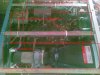
IC 1001 op amp B is the most suspect, what you had was a flash to ground on the probe, pin 7 (op amp B) of this chip has a low value resistor to ground, and would therefore be susceptible to anything bad happening on the ground line.

Also the zeners that are connected to the '358's, with the circuit powered check with a meter to make sure they have the voltage marked accros them (within 1/2 a volt or so), then check with a meter or better a tranny tester the pass transistors connected to the o/p's of the op amps, check the value of the associated resistors, check the voltage drop using a standard multimeter across all the diodes and just relpace all the electrolytic caps in that area (electro's are very common failiures in older gear), it might save time to actually replace all of the said components.
The fault could still be on the crt page 2, but without test gear I'd try the above.

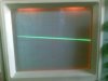
If you have another 'scope then try 'scoping all of the supply rails, if one of them shows a sawtooth type pattern of more than a 100mv or so then thats the culprit rail.

There are a few similarities between this and an older philips pm 'scope, I wonder if they used a philips chassis.
 
Last edited:
I had a better look, what I said is pretty much it for now, i cant really think of anything else.
 
Hi again .

I just want to thank you guys for the help .

The scope shows signals again after removing and reattaching the CRT tube , nothing was faulty after all .
 
Last edited:
Hi again .

I just want to thank you guys for the help .

The scope shows signals again after removing and reattaching the CRT tube , nothing was faulty after all .
Very valuable lesson there, BGAmodz. One we all need to remember...:woot:.

(Is there an avatar for "chagrined?")
 
Very valuable lesson there, BGAmodz. One we all need to remember...:woot:.

(Is there an avatar for "chagrined?")

Lol no chagrin from now on , only happiness with this scope .

I have read somewhere on the net that this scope can be used as component tester .

Is there a way to test for Cap ESR value ?
 
Maybe a bad connection on the tube socket eh.
 
Status
Not open for further replies.

Latest threads

New Articles From Microcontroller Tips

Back
Top