Continue to Site

Welcome to our site!

Electro Tech is an online community (with over 170,000 members) who enjoy talking about and building electronic circuits, projects and gadgets. To participate you need to register. Registration is free. Click here to register now.

  • Welcome to our site! Electro Tech is an online community (with over 170,000 members) who enjoy talking about and building electronic circuits, projects and gadgets. To participate you need to register. Registration is free. Click here to register now.

oatleye inverter

Status
Not open for further replies.

simoin

New Member
Hey everone,

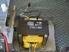
I have an old transformer at home and want to put together an inverter, i have found a kit at **broken link removed**, not sure if the transformer I have is the right sort, here's a picture.

There is also a link for the circuit diagram that you can download for free on that page, I'm not sure if it is sqaure wave or mdified sqaure wave. Why is it so much more expensive/harder to make a sine wave inverter?

Simon
 

Attachments

  • inverter-ups04.jpg
    inverter-ups04.jpg
    327.8 KB · Views: 790
I don't know if the transformer you have is suitable or not but I'll take a stab at part two.

Transformers in general are both current and voltage devices. When a transformer steps up a voltage, as it would in an inverter, it steps down the current. Let us say that we are going from 12 VAC to 120 VAC which is a voltage ratio of 10:1 The input current required to get 1 Amp out at 120 VAC is 10 Amps at 12 VAC, assuming 100% efficiency.

Generating 12 VAC at 10 Amps is what makes a sinewave inverter expensive. You must be very careful to design such a circuit so you minimize the losses which show up as heat. In practice you could never get 100% efficiency so the power in would always be greater than the power out.

If you want 240 VAC then the numbers get even pukier.
 
that makes sense, so basically it's too expensive and they are saving costs and selling crap square wave inverters to people. What happens when you put extra mosfets into the circut does that improve it from square wave to sine wave. Sorry if these questions are stupid but I am only learning still.

So how do I find out which transformers are compatible, from the reading I did it looks like the use tri-ordial ones and I think mine is not one of those... See picture above for details.
 
The kit tells you the spec's for the transformer it needs. Your pic of your transformer doesn't say anything about it, except it says when it was made.
Voltage? Current? Center-tapped? Power?

Crap square-wave inverters are cheap, efficient, stay fairly cool and work with most loads. Millions of nice Chinese ones are sold for a bargain price that you can't make one for.
If you need a sine-wave inverter then you need to live where electricity is stable and continuous. Here in my part of Canada the electricity goes off for a few minutes maybe every 10 years, then we celebrate in the darkness.
 
Crap square wave inverters work just fine in many applications. MOSFETS have relatively little to do with waveshaping by themselves. It all depends on what is around them. Like audioguru said since you can buy a squarewave inverter for less than the cost of the parts you should be sure that you need a pure sinewave inverter. Even so you may be light years ahead if you just buy one since your knowledge of electronis is not impressing any of us. Sorry mate.
 
Here is what some one would say from the old school about transformers for inverters. Transformers themselves make great inverters, they are very efficient, very reliable and produce very clean sign wave. In a since Tesla, westing house, Tomas Edison have been working with clean 60 cycle transformers for years. The problem is to get a clean solid state driver to work the transformer. High current liner transistors can to the job very well,but they are very expensive and are limited to about 40 amps. This is not enough current at 12 volt to a lot. So a type of SCR switching transistors is used. They can be good for almost 1000 amps. But they just switch the transformer on and off 120 time a second to sort of give you a square 60 cycle wave. So I say it not necessary a bad transformers, but it is bad solid state stuff that is use against tranformer.
 
A transformer does not make an inverter by itself. It just steps up the voltage from a power oscillator.

You cannot simply feed a low voltage sine-wave into a transformer to get a high voltage sine-wave out because then the transformer must be fed from a linear amplifier that will get as hot as the load. Then it wastes as much power as the load uses.
 
It looks like a standard issue UPS inverter transformer Likely in the 250 VA - 350 VA capacity range. If so its already wound for a 12 volt input source. One advantage is that typical UPS transformers are designed to take considerable overloads for short periods. Most are capable of supporting 2 - 3 times their continuous capacity for around 5 minutes or so.

If the UPS origionaly used a 12 volt battery you already have all the inverter you need already to go. It just needs a bigger battery in order to work for longer periods.

Why design a less efficient and less capable inverter when you already have one there?
 
Status
Not open for further replies.

Latest threads

New Articles From Microcontroller Tips

Back
Top