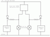
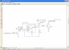
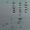
I bought new motorcycle mirrors with sequential turn signals built in. The problem is my flasher wont let them complete. Flasher is an electronic package with built in canceler. I would like to run my running lamp wires(no longer used) to the turn signals through an SCR triggered by the flasher circuit with a transistor in series with the SCR so when it senses nothing from the flasher it will in essence turn of the SCR. I know it will need an r/c circuit to keep the transistor conducting during the flasher off time, but I don't know what configuration the transistor should go and how to incorporate an r/c circuit or the flasher input into it. Any help will be greatly appreciated. Thanks, adown
Continue to Site
 This isn't the first time I've been told that. I believe the canceler works on the tipping motion of cornering. It is in plastic box that contains the whole turn signal apparatus. I thought about cutting in to it but I'm still under warranty and also can't readily get to it.