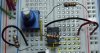
Here is a picture of the circuit in question.
**broken link removed**
I am running the op amp on 0 to 5 volts, in non-inverting mode
Put simply, the output is unchanging as I adjust the voltage at the non-inverting input. _The top 10k resistor and the blue 8.8k (measured) pot, produce a voltage on the yellow wire that swings between gnd and about 2.38 volts. _The blue strips are gnd, and the red strip is 5.15 volts.
With the 2k feedback, and 1k (other) resistor it should have a gain of 3, but as I adjust the input voltage, the output stays constant at about 4.68v. _If I remove the other resistor (between invert and gnd) it works as a voltage follower, swinging between 1.92v and about 4.68v. _I have tried this circuit with four op amps; three from Fairchild, and the one pictured from National.
Is there any reason why this is not working?
Thank you for your time and consideration.