Continue to Site

Welcome to our site!

Electro Tech is an online community (with over 170,000 members) who enjoy talking about and building electronic circuits, projects and gadgets. To participate you need to register. Registration is free. Click here to register now.

  • Welcome to our site! Electro Tech is an online community (with over 170,000 members) who enjoy talking about and building electronic circuits, projects and gadgets. To participate you need to register. Registration is free. Click here to register now.

Newbie questions

Status
Not open for further replies.

HaroldPudwell

New Member
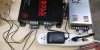
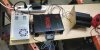
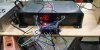
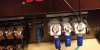
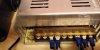
I'm trying to amplify ultrasonic sound by using feeding the output of a ultrasonic sound generator to a 400W 4 channel car amp. The car amp is being powered by a AC/DC converter that outputs 12V @30A. I have connected 4 500W mini high frequency tweeters to the channels. All parts are new and have been tested. The ultrasonic sound generator will create sound when hooked directly to the tweeters but not through the amp. I wired the sound generator output to all 4 channel inputs on the car amp. The light on the sound generator only illuminates when connected to the car amp or a tweeter. The green led on the car amp illuminates briefly when the power is turned off and is not on when the device is powered up. The car amp is rated to 22,000hz. I get no sound from this setup and do not understand why. My first thought is that the ultrasonic sound generator is not designed to be amplified.
 

Attachments

  • IMG_20191103_185714.jpg
    IMG_20191103_185714.jpg
    605.4 KB · Views: 112
  • IMG_20191103_185534.jpg
    IMG_20191103_185534.jpg
    952.3 KB · Views: 100
  • IMG_20191103_180320.jpg
    IMG_20191103_180320.jpg
    1.4 MB · Views: 100
I believe you may have the power input connections to the amp connected wrongly?

You have green connected to mains ground; that should be PSU DC negative. I cannot tell from the photos what the PSU terminals are.

Both black and white on the amp should be PSU DC positive; black is the main positive input, white is remote on/off control.

(I have no idea how the amp will respond with only the tweeters connected, it depends very much on their characteristics and also the output characteristics of the ultrasonic generator).
 
You should also be aware that the claimed output figures for such amps are wildly imaginary, and as you say the amp is filtered off at 22KHz it's probably removing most of the ultrasonic content anyway.

The power connections between PSU and Amp seem rather thin as well, although like rjenkinsgb I've no idea what the connections actually are.
 
you have the remote wire on the power input of the amp wired to a terminal on the power supply. it also looks like the amp ground is connected to the AC input ground, but not connected to the minus or common terminal on the output of the power supply. since such power supplies have floating outputs, the negative of common terminal of the supply is not connected to frame ground. this is why the amp doen't turn on. there should be a switch between the +12V terminal on the amp and the remote terminal, so you can use the switch to turn the amp on and off without having to plug and unplug the power supply . it might be helpful if we knew what the terminals on the power supply were labeled as.

you didn't mention the impedance of the tweeters, but that amp delivers 38W (per channel) into 4 ohm loads, and 75W/ch into 2 ohm loads (the specs should be listed in the owner's manual). the amp is a class AB amplifier, so that 22khz spec is probably the amp's natural rolloff characteristic.
 
The tweeter impedance is 4ohm. They can be doubled on each channel with a capacitor. Here are better images of the terminal labels. I believe I have it correct. I'm temporarily using the surge protector switch for my switch until I get it working. I then plan to us a wifi smart plug to control remotely.
 

Attachments

  • IMG_20191104_164729.jpg
    IMG_20191104_164729.jpg
    1.3 MB · Views: 96
  • IMG_20191104_164715.jpg
    IMG_20191104_164715.jpg
    791.6 KB · Views: 96
You definitely have the wires from the PSU to the amp on the wrong terminals.

At the power supply, move the amp green to the "V-" terminal section and both black and white to the "V+" section.

Don't change the terminals the cable from the wall plug is using, they are correct.

(As the amp is intended for use in a car, the "GND" terminal related to the vehicle ground, which is battery negative).
 
Status
Not open for further replies.

Latest threads

New Articles From Microcontroller Tips

Back
Top