Continue to Site

Welcome to our site!

Electro Tech is an online community (with over 170,000 members) who enjoy talking about and building electronic circuits, projects and gadgets. To participate you need to register. Registration is free. Click here to register now.

  • Welcome to our site! Electro Tech is an online community (with over 170,000 members) who enjoy talking about and building electronic circuits, projects and gadgets. To participate you need to register. Registration is free. Click here to register now.

Newbie questions about Sound amplifier

Status
Not open for further replies.

Quasar999

New Member
Hello
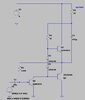
i'm a beginner and i have a question about the following schematic.
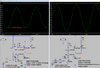
I can't understand the use of first transistor at the input; if the audio input is sinusoidal the amplifier exit from active state every time the signal become negative and the signal will be clipped. I'm missing something?
 

Attachments

  • Sch2.jpg
    Sch2.jpg
    63.7 KB · Views: 203
I'm missing something?
Yes, feedback from the output DC level to the input through R1. There is a current path from the Q2-Q4 emitters, through R1, through the Q1 base-emitter junction, to GND. This DC feedback is a positive current into the Q1 base. In order for the input stage to clip, the input signal negative current through C1 must be greater than this feedback positive current.

The input sine wave signal may go below GND, but that is to the left of the input coupling capacitor C1. Q1 inverts the signal, and the output stage (Q3-Q4) does not, so the feedback through R1 is negative feedback. That feedback sets the voltage gain for the signal and stabilizes the DC operating point of the output stage at approx. Vcc / 2.


ak
 
There is a DC offset across the input coupling capacitor, with R1 providing enough base current to keep the transistor partly turned on.

As long as the input signal is not excessive, the transistor will always be conducting to some extent and the output will be an inverted but amplified version of the input.
 
Thx. Anyway i did a simulation with spice but something seems wrong. The circuit works with no only using a signal of amplitude 1mV and using a resistor of 1k for R1. What do you think?
 
Thx. Anyway i did a simulation with spice but something seems wrong. The circuit works with no only using a signal of amplitude 1mV and using a resistor of 1k for R1. What do you think?

I think it's a really crappy and non-viable circuit - it's probably about the second 'example' you get in text books, so is just to explain a principle rather than actually work.
 
The amplifier was missing an input resistor and its value for R1 was wrong. My fixes reduced its distortion and increased its maximum output power 2.5 times but its power is still puny.

Then I made it even better:
 

Attachments

  • amplifier with very low power.png
    amplifier with very low power.png
    43.1 KB · Views: 221
  • improved amplifier.png
    improved amplifier.png
    26.5 KB · Views: 180
I made some changes to the circuit and spice simulation seems good. What do you think?
 

Attachments

  • Sch2c.jpg
    Sch2c.jpg
    298.4 KB · Views: 187
Why would you imagine totally random changes are going to help anything?. Although I'm pleased to see you added bootstrapping.
I’ve added a resistor to the emettitor of q1 to adjust the bias voltage on the base. Then added a resistor from main supply to adjust the bias current on the base. Changed the resistor on the feedback cause the change of the voltage.
Which weakness has mine version? The simulation seems good.
 
I’ve added a resistor to the emettitor of q1 to adjust the bias voltage on the base. Then added a resistor from main supply to adjust the bias current on the base. Changed the resistor on the feedback cause the change of the voltage.
Which weakness has mine version? The simulation seems good.

All three of those changes are just crazy - I've no interest in what simulations might show, only what real life does.

AG has already added changes to make it about as usable as possible, what was wrong with those?.
 
Your modified circuit has an input of 0.5V peak but your output is less at 0.4V peak. Then it does not amplify, instead it attenuates.
Its output power is a whopping 0.005W.

I modified your latest circuit to work much better:
 

Attachments

  • improved again amplifier.png
    improved again amplifier.png
    52.9 KB · Views: 213
I made some changes to the circuit and spice simulation seems good. What do you think?
R1 is best left at a much higher value.... 100 ohms is much too small and provides so much feedback that you don't have any gain... in fact there's so much negative feedback there that it's going to load down your input signal as well. AG's choice of 230k provided plenty of gain... each component has a specific purpose for being there, and a specific reason why it's whatever value it is. that's why people are telling you arbitrary part value changes are not a good idea... i would also add that if you are going to tweak a part value to see how it changes the operation of the circuit, focus on one part at a time, and don't make huge changes... a 5 to 10% change in a part value is usually enough to "balllpark" it to see if it improves the performance or not. if you change 3 part values and the circuit stops working, you don't know which change(s) caused it, so only work with one part, and if you get it to improve the performance, then make a change to another part... if you change 3 parts and the circuit stops working, you're likely to get lost in guesswork which change caused the problem.
 
All three of those changes are just crazy - I've no interest in what simulations might show, only what real life does.

AG has already added changes to make it about as usable as possible, what was wrong with those?.
Nothing. I‘m a beginner and just try to understand what are the good and bad.

Thx to audioguru for the support.
 
You need to learn about Ohm's Law and the Power Law.
Learn about the current gain listed in the datasheets of transistors.
Learn about common collector and common emitter transistor circuits.
Learn about the few ways to make a transistor power amplifier.
Learn about speakers. Almost all home speakers are 8 ohms, car speakers are 4 or 2 ohms. but your speakers were 25 ohms that I have never seen and 15 ohms that were used 60 years ago.
 
15 ohms that were used 60 years ago.
some guitar amplifiers (vacuum tube type) into the 70s still had a 16 ohm tap on their output transformers... apparently wiring cabinets in series was still a thing until then.
 
some guitar amplifiers (vacuum tube type) into the 70s still had a 16 ohm tap on their output transformers... apparently wiring cabinets in series was still a thing until then.

It still is - series, parallel or series/parallel are still all used.

Historically, and generally, valve amps used 16 ohm speakers (didn't matter what you used, as you simply wound the transformer accordingly), and as it was impedance matched (lowest possible efficiency) there was no damping factor. Transistor amps tended to use 8 ohm speakers, to give increased power with no transformers, much greater efficiency, and provided damping as well. Car radios tended to use 4 ohms, again to give more power from the very low supply rails.

The 25 ohm speaker that AG has never seen was 'fairly' common in cheap tiny radios, giving only very low power and extended battery life.
 
Status
Not open for further replies.

Latest threads

New Articles From Microcontroller Tips

Back
Top