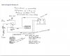
Newbie needs help! on an explanation of a High/Low speed circuit on a electronic motor controller for a commercial electric vehicle. I have uploaded a file that shows the circuit and a file that shows a capacitor that was in the HI/LO module. The module is connected between controller B- and #2 on the controller. The capacitor is a #104 and there is supposed to be a zener diode also in the circuit to somehow reduce the voltage from the accelerator (5.5 to 11.0 volts. The module that is supposed to be connected to the 104 cap. is supposed control the voltage to a fixed amount to approx. midrange of the (5.5 to 11.0 volts) no matter what position the throttle accelerator is in. This circuit is to be used for reverse on the electric vehicle to control the speed. Please check the schematic and tell me what Zener diode and capacitor or what I can use to reduce the speed in the circuit. Thanks, Ted
Continue to Site