Thunderface
New Member
I have a Kids Battery Powered vehicle I want to upgrade.
It is 12V & I want to convert it to run faster & for longer. I will use a Dewalt 20V battery to power it. I have purchased an adaptor with an inline 30a amp fuse for the battery. I also purchased a voltage controller to dial the speed of the motors as desired.
https://www.amazon.ca/gp/aw/d/B0995KCNB4/ref=ya_aw_od_pi?ie=UTF8&psc=1
https://www.amazon.ca/gp/aw/d/B08R7H4D3K/ref=ya_aw_od_pi?ie=UTF8&psc=1
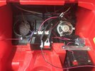
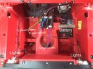
As far I know this will work to speed up the motors (which i will up grade to 24V motors). My concern is the electronics in the car. The lights & stereo. I would like them to continue to run on 12V. I've read that a buck converter could be used to drop down the voltage before it gets to the electronics. Something like this:
https://www.amazon.ca/gp/aw/d/B078Q1624B/ref=ox_sc_act_image_1?smid=AFHAE9RJVUMB&psc=1
or this
https://www.amazon.ca/gp/aw/d/B076H3XHXP/ref=ox_sc_saved_image_2?smid=A3JJM7S8SDXVXM&psc=1
But I don't know where to add this in the circuit.
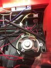
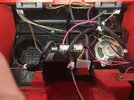
From what I can see, the best place to put it is somewhere after this 7 pin connector coming from the main circuit board. Its where all electronics get powered from. Any thoughts how I can do this?
It is 12V & I want to convert it to run faster & for longer. I will use a Dewalt 20V battery to power it. I have purchased an adaptor with an inline 30a amp fuse for the battery. I also purchased a voltage controller to dial the speed of the motors as desired.
https://www.amazon.ca/gp/aw/d/B0995KCNB4/ref=ya_aw_od_pi?ie=UTF8&psc=1
https://www.amazon.ca/gp/aw/d/B08R7H4D3K/ref=ya_aw_od_pi?ie=UTF8&psc=1
As far I know this will work to speed up the motors (which i will up grade to 24V motors). My concern is the electronics in the car. The lights & stereo. I would like them to continue to run on 12V. I've read that a buck converter could be used to drop down the voltage before it gets to the electronics. Something like this:
https://www.amazon.ca/gp/aw/d/B078Q1624B/ref=ox_sc_act_image_1?smid=AFHAE9RJVUMB&psc=1
or this
https://www.amazon.ca/gp/aw/d/B076H3XHXP/ref=ox_sc_saved_image_2?smid=A3JJM7S8SDXVXM&psc=1
But I don't know where to add this in the circuit.
From what I can see, the best place to put it is somewhere after this 7 pin connector coming from the main circuit board. Its where all electronics get powered from. Any thoughts how I can do this?
Attachments
-
 AA07F230-400B-44B3-8AA7-746BC3FB3C48.png604.8 KB · Views: 379
 -
 E7321503-86BC-470B-B082-B1C04EAEA4C6.jpeg300.6 KB · Views: 346
 -
 6DCBD19F-3E40-4C1C-8629-6BCF971F1B0D.jpeg301.5 KB · Views: 390
 -
 C71D14E7-405B-4718-9586-E6B2D9AEDD6D.jpeg260.9 KB · Views: 397
 -
 383A5F87-F93D-47A9-88D4-A75D7F598651.jpeg290.3 KB · Views: 482
