Continue to Site

Welcome to our site!

Electro Tech is an online community (with over 170,000 members) who enjoy talking about and building electronic circuits, projects and gadgets. To participate you need to register. Registration is free. Click here to register now.

  • Welcome to our site! Electro Tech is an online community (with over 170,000 members) who enjoy talking about and building electronic circuits, projects and gadgets. To participate you need to register. Registration is free. Click here to register now.

New Project time!

Status
Not open for further replies.

jrz126

Active Member
Now that summer is here, I have alittle more free time, so I think its time for a new project.

Many of you have seen my LED project for my car...https://www.cardomain.com/ride/435572/2
I'm looking to add even more LED's :)

Here's what I had in mind...hacking this led display thingy that I bought awhile back **broken link removed**, just using each bar for the convience of not having to make up my own housing for the LEDs. I'll replace them with Blue Leds, and mount them in various places throughout my car.

Now just turning on and staying on constant is too simple for me, I'd like a way to have them light up with the music. I'd like to make a simple interface to do this, possibly only having to run 2 wires to each bar. Then by changing the voltage sent to the bar, it will determine how many leds light up. (say I send +5V, 1 led lights, then I up it to 6V and 2 leds light. ect.)
I remeber doing something similar to this in my EE lab. What we did was placed a regular diode in with the LEDs and used the forward voltage drop of the diode to control the voltage at which each diode turns on.
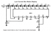
Here's a schematic, the 1n4148s are my leds and R1-R8 are the current limiting resistors (values to be determined).
Does it sound like this will work?

oh yeah, my leds have a forward voltage of 3.5V and normal current of 20mA
 

Attachments

  • diodes.jpg
    diodes.jpg
    28.5 KB · Views: 1,401
Hi Jeff,
The LEDs in your circuit will change their brightness a lot with a changing input voltage.
National's circuit needs a supply voltage doubler, uses 2V LEDs but can drive five or six 3.5V LEDs and should look pretty good:
 

Attachments

  • lm3915.png
    lm3915.png
    18.8 KB · Views: 1,404
thanks for the reply Mr Guru, I'm aware that the brightness of each LED will vary, but I was planning on hiding the led bars themselves and just using the reflected light. So the varying brightness will be good.
Also, I dont have much room to stick an IC in there, and I want to keep it as simple as possible by only having to run 2 maybe 3 wires to each bar.

Now for something kind of different....
I drew up a schematic of the original circuit used to drive the LED's, where exactly does the pic get it's clock from? I'm assuming its just a simple RC circuit? (also pins 15 17 18 5 and 6 arent used, I just used a wire to indicate that.)

Would it be possible to have the pic run off the clock of my roof LEDs (the output of a lm3915)?
 

Attachments

  • led_bars.jpg
    led_bars.jpg
    26.4 KB · Views: 1,362
go to talkingelectronics.com interactive site

they have a Stereo VU meter with the circuit diagram. It converts sound into a visual volume indicator. The louder the sound, the brighter the LED.
 
Talking Electronics have an LED RF Power Meter project that rectifies RF and changes the brightness of an LED according to the level. Its 100pF input capacitor is much too small for audio frequencies.

They also have a Stereo VU Meter project that works about the same as the bar-graph circuits that Jeff and I posted since it changes the number of lighted LEDs according to the level. Like the LM3915, it doesn't change the brightness of the LEDs.
 

Attachments

  • talking_electronics.gif
    talking_electronics.gif
    15.4 KB · Views: 1,351
Jeff,

In your diagram (diodes.jpg), I would replace the resistors with constant current ICs such as the LM334 so the brightness of the LEDs is constant.

Len
 
oh yeah forgot to mention that those 8 resistors are actually connected to some transistors to supply extra current in the orignal circuit, not the diodes.jpg
But I'm just wondering if it possible to have the clock for the pic be generated by an Lm3915 so that the pic would respond to the music as well.
 
You might need to level-shift and speed-up the output of the LM3915 with a Schmitt-trigger inverter. :lol:
 
Instead of having the LM3915 drive the clock input of the PIC you could have it drive a timer input. This would let you vary your speed through software without messing with the temperamental clock input.
 
The pic is pre-programmed, it's actually a CF745-04 but I found a datasheet that said it could also be the one I used in my schematic. Also, I've never programmed a pic before, so I think thats out of the question for now.


You might need to level-shift and speed-up the output of the LM3915 with a Schmitt-trigger inverter.

Ummm...do you have a schematic? :lol:
 
Hi Jeff,
I don't remember seeing a schematic of how your LM3915 is powered or what it is driving. Adding a Schmitt-trigger inverter to its output to level-shift and speed-up its output is dependent on it. A single inverter from a CD74C14 hex Schmitt-trigger inverter package might need a pullup resistor on the output of the LM3915, a series resistor from the output of the LM3915 to its input, and another inverter to have the correct polarity.
 
Ok, I finally have the schematic for the circuit that Im using for my leds.
The clock and data in for the shift registers are attached to one of the counter ic's

So no how would I hook it up?


EDIT: I know Im missing a few connections on the counter IC's...too lazy to finish it in pspice
 

Attachments

  • logic_110.jpg
    logic_110.jpg
    65.8 KB · Views: 1,240
Hi Jeff,
Since you aren't using the LM3915 as a VU meter, level shifting isn't necessary, in fact even the fairly expensive 18 pins LM3915 could be replaced by a cheap 8 pins single-supply opamp wired as a comparator.

The 2nd half of the opamp (dual one) could buffer and amplify the output of the 2N2907 circuit, drive a transistor and change the supply voltage to the LEDs so that their brightness follows the volume of the music. :lol:

What will the Pic do?
 
The pic changes the patterns that the leds light up and makes them flash. I figure if I can control the clock of the pic with my audio signal then it will appear that the leds flash with the music. Is it possible to run a pic like that?

I think I'll just leave my roof circuit as is, it works right now, but if I play with it Im sure I'll manage to break it. Also, I'm drawing about an amp through my 5V supply, so it would have to be a pretty hefty transistor.
 
Hi Jeff,
Your circuit is wasting a lot of power by using only 5V for its supply. The Cmos ICs work with a supply up to 18V to 22V depending on their manufacturer. A lot of waste could be saved if you wired your 3.5V LEDs in series groups of 3. A simple Pulse-Width-Modulation circuit can dim the LEDs without much waste. :lol:
 
jrz126 said:
The pic changes the patterns that the leds light up and makes them flash. I figure if I can control the clock of the pic with my audio signal then it will appear that the leds flash with the music. Is it possible to run a pic like that?

PIC's can have the oscillator speed changed whilst running, and will work from DC up to their maximum speed. By using an exernal voltage controlled oscillator you could vary the speed of the PIC over a VERY substantial range.
 
Are you trying to create a simple LED stereo VU meter?

Skimming through this thread I believe it seems your trying to build a Stereo VU meter with LED's. If this is right, I've built exactly that using two OP amps, resisters and schmit trigger IC's. It works good and only requires a 5Vdc source with the parts mentioned above.

Simply, it takes the music, amplifies it via the op amp (2 op amps for stereo VU), then feeds it resistively into the input on a schmit trigger (each input with a various resistor size). Then all LED's are attached to the 5Vdc source and grounded at the output leads of the schmit trigger. When the amplified music and resistor aquire enough to flip the schmit trigger, that paticular LED lights proceeded by lesser resistors elsewhere.

If this sounds of interest, post me back a reply and I'll get a schematic posted for you.
 
That's what an LM3914 (linear), LM3915 (log) and LM3916 (VU meter scale) do with hardly any additional parts, and they drive 10 LEDs.
 
ok, so going back to the schematic of the pic, what is the clock speed of it right now? could it just use a simple RC circuit as the clock?

Also, I know Im wasting power with my current configuration, but if I did wire them in groups and a led went bad, I'd lose that entire group. This way I'd only lose the single led.
 
Status
Not open for further replies.

New Articles From Microcontroller Tips

Back
Top