Electronman
New Member
Hello guys,
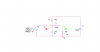
To see how a speaker cone does vibrate on a circuit with a single ended power supply I designed the bellow to see if the cone does the negative vibration.
The strange thing is that there is a NEGATIVE swing at the load (RL) too??!
I am wondering how it does happen while there is no any split power supply or divider?
I thought maybe the collector of the transistor and the R1 are creating a voltage divider but soon I noticed the voltage divider is not able to case a negative voltage at RL because the other pin of the RL goes to the ground. I mean the RL is only able to swing between the positive and ground.
Any idea please?
")


")
