bogdanfirst
New Member
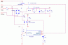
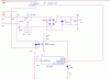
ok. i have this circuit. it uses a PIC(not shown in the diagram) to drive some lamps trough a triac. the cicuit is intended to work only with exact connections for Phase and Ground. i want to make the circuit work even if the mains connections(phase and ground) are swapped. so i need to drive the triac with an optoinsulator and figure a way so that i don't have the phase connected to the PIC directly in case the mains ground and phase are swapped.
the pic is not shown in the figure. the optocoupler is used to provide syncronization with the phase for the pic. the triac is driven from the pic directly.
the pic is not shown in the figure. the optocoupler is used to provide syncronization with the phase for the pic. the triac is driven from the pic directly.