Continue to Site

Welcome to our site!

Electro Tech is an online community (with over 170,000 members) who enjoy talking about and building electronic circuits, projects and gadgets. To participate you need to register. Registration is free. Click here to register now.

  • Welcome to our site! Electro Tech is an online community (with over 170,000 members) who enjoy talking about and building electronic circuits, projects and gadgets. To participate you need to register. Registration is free. Click here to register now.

Need some help modifying a PC fan controller slightly

Status
Not open for further replies.

BrentNewland

New Member
Newegg.com - NZXT SEN-001LX Sentry LX Aluminum dual bay fan controller - Controller Panels

The controller has five fan channels running at 12v 4watt (0.3a).

Newegg.com - Scythe DFS123812-3000 "ULTRA KAZE" 120 x 38 mm Case Fan - Case Fans

The fans require 0.6a at 12v. The PC has 5v and 12v (DC, of course) available inside.


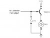
Now, I've got a very basic grasp of electronics, but I don't know a whole lot. What I would like to do is double the power going from the fan controller to the fan, which should let the fan controller use the fans to the maximum. From what I can tell, I would need to wire a transistor inbetween the fan controller and each fan. Is that right? If so, what kind of transistor would I need, and how would I hook it up (i.e. which pin would go to the controller, which pin would go to the fan, which wire would it go on - I'm assuming positive, and where does that third pin connect to)?


The other thing I would like to do with it is replace the coin battery with two AA batteries (the battery inside is a 3v CR2032, so I should be able to get a standard battery holder for two AA's and hook them up in series. However, I would rather not replace these at all (a rather large inconvenience and a safety risk, if the battery is dead the fans die and the computer overheats). It would be great if I could get the batteries to recharge while in the socket and in use (and I found a diagram at USB Battery Charger Circuit which would assist a bit, but I can pull 5vDC directly off one of the power connectors so I need to worry more about having too much power than not enough). But I can't seem to find any circuit diagrams showing a battery recharger for active use. I imagine I would need a 5v voltage regulator (like the kind that goes in a car between the alternator and the battery)... but I wouldn't even know where to begin modifying or creating from scratch a circuit that could do that. And failing that, it would be nice to at least have some sort of voltage indicator so I know when to replace the batteries (maybe wired up to a LED that turns on when the battery is low?)


So, anyone want to help a poor soul out?
 
Hi Brent,

your description is a bit fuzzy to me.

First off, why would you want to connect a 0.5A fan to a battery? A CR2032 would be dead in no time. Secondly you can't charge that kind of battery!

You have a quite a lot of power from the PC power supply (least power 350W, stepping up to 650W).

PC fans are normally supplied with connectors (one male and one female) to connect directly to the PC-power supply without losing a power connector e.g. for a HDD.

If you require more power connectors purchase a Y-connector, which is a male plug with two cables out on two female plugs which fit for HDD drive power connectors.

Regards

P.S. Don't manipulate the on board CR2032. It is the backup battery for the real time clock, and parts of your CMOS-Setup!

Boncuk
 
Last edited:
If your coin cell battery is going dead that fast either you are using bad replacement batteries, the wrong type of replacement batteries or you have a problem else were.
That coin cell typically lasts around 5 - 10 years on a computer.
 
Sorry if my description was unclear. The CR2032 isn't the same as the motherboard battery, it's on the fan controller (which is a separate unit). The CR2032 tends to die on that fan controller every three months (you can check out the reviews at the first link, it's a common problem). When that battery dies, the fan controller doesn't turn on when you turn the computer on, which means the computer overheats.

The fans ARE powered by the power supply, through the fan controller, but the fan controller only puts out 0.3A and the fans need 0.6A to operate at full speed, so I need to increase the power to the fans(while still having them controlled by the fan controller so they don't run at full speed all the time).

So I need to turn 12V 4W 0.3A into 12V 8W 0.6A, and I need to replace a coin battery with some high capacity AA batteries so I'm not replacing them that fast.
 
Use a couple of AA batteries instead of the coin cell. The coin battery is for the clock and user settings. It drains fast probably because it's poorly designed. A set of AA should last it for ages.
 
Yes, that's what I am planning on doing. But I'd either like to figure out how to recharge them while they're in the computer and simultaneously provide power to the device, or power the device off the computer and have the battery kick in when the power goes off. Any way to do that?


Regardless, that's the least of my concerns. MY bigger concern is how can I double the power being output by the fan controller so the fans are capable of operating at their maximum speed.


*edit* Think I figured out a way to have power from the computer and the battery... a 3v relay? Besides running power from the computer's power supply to the spot on the PCB that the battery connects to, I run a line from the computer's power to a relay and wire it so that when the computer's power cuts off the relay brings in the battery, and when the power comes back on it isolates the battery. Would the short period for the relay to engage the battery after the power goes off cause the fan controller to reset? could I avoid this with a capacitor?

*edit 2* instead of using a relay would it be easier to just hook both the battery and the power from PC to the same location, but place a diode on each line so that they don't interfere with each other?
 
Last edited:
Does the fan controller control the speed of the fans, or does it turn them on/off completely as needed, or not needed? If it controls the speed of the fans, does it do so by turning them on/off at varying duty cycle, or by a variable DC voltage?

To achieve greater power to the fans, what it boils down to is that the controller's output to a fan instead controls an input to a circuit that uses full power from the computer to power the fan. The details of the circuit depend on the following:

1. The controller's output characteristics, as asked above.
2. The power supply voltage that will provided full power to the fans. I believe that is +12 Vdc.
3. The fan characteristics. I believe that is given in a link you provided.

I shall assume that the power supply is capable of delivering full power to the fans.

As for the battery, I agree with blueroom, that if a coin cell will last for 3 months, 2 AA cells will last for a lot longer, 2 C cells, much more longer. That is going to be easier than a charging circuit for rechargeable batteries.

Your relay idea to switch between computer power and battery could work with a capacitor to stand in for the time for the relay contact to switch from one position to the other. I assume the voltage from the computer is correct for powering whatever the battery feeds power to. If not, you will need a voltage regulator to drop the voltage to the proper level.
 
Fans are three wire. One sends RPM to the fan controller, one is ground, one is power. Fan controller controls the fan by adjusting the power (less power, slower speed). The fan controller is separate from everything else in the computer, it only receives power from the power supply (no motherboard or peripheral interactions, fans are powered from the fan controller and are not connected to anything else). I am assuming that if I double the power output going to each fan the fan controller will still be able to compensate (thanks to being able to read the RPM), only problem being that the fans need twice the power the controller can supply (hence the need to double the power).

The computer has 5v and 12v on all molex connectors, I was planning on using a resistor (or a few) to drop the 5v down to 3v. And hopefully it wouldn't fry the fan controller. It may be easier to just wire up a charge indicator to flash when the battery gets low, there are plenty of diagrams for that online.
 
It's still important to know why the controller only delivers 4 watts to each fan. Computer fan speed is usually adjusted by switching 12v power to the fan on and off at a variable duty cycle. It seems to me that a controller design would naturally use the computer's power supply to directly to provide power for the fans, anyway. Is it that the duty cycle never gets to continuous on at +12V, or is it that the controller cannot output +12V at .6A (i.e. the voltage drops below +12V)? Is it that the maximum RPM of the fan is limited, no matter what fan you use? If you have a voltmeter you can measure the DC voltage at the fan to help answer that question with the fan and its probe physically separated from each other and the controller temp adjusted to minimum for that probe so that the controller will output full power to the fan. The temperature of the probe should be made to be above the set temperature by warming it, if necessary. You can then see if the voltage is a full +12V, or some other voltage. Do this with a .3A fan (or smaller) as well, and see if there is a difference in the voltage at the fan. There is a reason the controller only outputs 4 watts and it may have nothing to do with limitations on the capacity of the power supply.
 
The maximum RPM isn't supposed to be limited, near as I can tell, it's that the controller itself can't output that much power (it has to control five fans plus a full color display and temperature probes). At least, that's what I've read on the comments on that fan controller.

I would test it with a multimeter, but it's inside my new PC case, which has no power supply (or fans) yet.
 
You can try the attached circuit to boost the current output of the controller. Depending on the controller's output, you may not need the 10K resistor.
 

Attachments

  • fan.jpg
    fan.jpg
    56.5 KB · Views: 538
Last edited:
I can't hurt to try it, but I can't guarantee it will work. The controller output may not be a voltage. The controller output may be a FET with source connected to ground and drain connected to the low side of the fan, requiring the other side of the fan to be connected to +12V. Or, something else. There's just not enough info on the controller output to know. It would help to know if one the pins on the connector that mates to the fan always has a solid +12 volts on it (and I mean solid, because the tach output might be pulled up to +12V, which is not solid). If it is a FET pulling the low side of the fan toward ground, then you will need a different booster circuit configuration. Get a TIP30 transistor while you are at it, to cover that possibility. Maybe you can write down the part number from an IC that's involved in the output to the fan. I'm sorta shootin in the dark here.
 
Last edited:
Status
Not open for further replies.

Latest threads

New Articles From Microcontroller Tips

Back
Top