Continue to Site

Welcome to our site!

Electro Tech is an online community (with over 170,000 members) who enjoy talking about and building electronic circuits, projects and gadgets. To participate you need to register. Registration is free. Click here to register now.

  • Welcome to our site! Electro Tech is an online community (with over 170,000 members) who enjoy talking about and building electronic circuits, projects and gadgets. To participate you need to register. Registration is free. Click here to register now.

Need quick help on magnetic levitation circuit

Status
Not open for further replies.
Last edited:
What's the frequency now with the extra feedback? If you add a small cap between + input and gnd you can slow the switching freq a bit (maybe 300 to 500Hz?), this will stabilise it further as it will give more movement of the floating magnet and larger waveform from the hall sensor.
 
Maybe my question was slightly ambiguous, I meant for you schematic are the pins arranged as they would be as pins 1, 2, and 3 or are they in no particular order.
 
I thought the schematic was clear enough, as schematics go.
If you go back to the schematic in post #19 i have changed it to include the hall sensor pin numbers, and in order of pinout.

I have built a second unit and this time payed more attention to getting the hall sensor mounted to the centre of the coil, and the coil vertical, and no longer have the jitter problem that was evident in the previous unit.

Also found a thick metal plate (or several washers) mounted on the coil face that the hall sensor is mounted on will increase the coil magnetism.

There is no hard fast rules with this project except to get it working and then play with principles to see if you can improve the strength or the coil's operation.

Pete.
 
Across the weekend i managed to get a coat of paint on the project dry and it reassembled, then started another one.

Here are a few photos.

The circuit board is the earlier version that just used an LM358 opamp and the drive transistor, to show how simple it is to get this to work.

The coil is just one i wound around a small bit of copper tube, by sticking a bolt through it and placing it in the cordless drill.

A thick metal plate on the bottom is needed for the magnet to attract to (could be a few washers), the hall sensor was mounted in a plastic washer for ease of mounting but a dob of glue would work just as well.

All very simple isnt it?

Pete.
 

Attachments

  • 019 small.jpg
    019 small.jpg
    29.5 KB · Views: 352
  • 031 small.jpg
    031 small.jpg
    25.4 KB · Views: 369
  • 037 small.jpg
    037 small.jpg
    40.4 KB · Views: 368
  • 006 small.jpg
    006 small.jpg
    42 KB · Views: 373
  • 011 small.jpg
    011 small.jpg
    39.3 KB · Views: 364
  • 015 small.jpg
    015 small.jpg
    32.3 KB · Views: 353
I take it from your comment you are trying to use an inductor for a coil.

I had tried one and it did not work for me, i really dont know the answer to your question, so can only surgest you try it and prove me wrong, but dont be suprised if it dont work. :(

Pete.
 
wouldn't you just spin it with your hands? or maybe you could apply the homopolar motor, though you'd have to research a bit more about that one
 
Some objects look to hover forwards and backwards at times on their own.

I guess you could add 2 small weaker magnets to the base of the globe and have say 3 or 4 small coils in the base of the gadget and rotate the coils in sequence, similar to how you drive a stepper motor.

Or use a small stepper in the base with a magnet attached to the shaft and a second magnet in the base of the globe.

My moon rock (ball of crinkled alfoil) moves around with a slight movement in the air, although it normally goes 90 degrees one way and then reverses 90 degrees the other way.

I have RGB leds above and below that scroll through the 7 colours, that reflect off the moon rock and gives a novel display, also put a magnet on a piece of acrylic clear rod that glows with the coloured leds, looks like a floating icicle.

Pete.
 
I did see one idea of using a tea candle below a turbine shape object, and the heat from the candle made it spin, perhaps not a good idea for a polystyrene ball.
 
The schematic is definitely correct right? I've tried the schematic with the exact parts and values but it doesn't seem to be working :S Wonder what I'm doing wrong
 
Have you got the coil wires around the right way, (i cant show that in a schematic) try swaping the coil wires around.

What magnet are you using?
What coil are you using? (earlier you implied you had an inductor for a coil and i said it would not work)
You do have the hall sensor facing the correct way? (flat side towards the coil, shafered side towards the magnet)

So you can check the schematic here is the PCB i made and it worked fine.

Pete.
 

Attachments

  • Levitation PCB 001.JPG
    Levitation PCB 001.JPG
    59 KB · Views: 409
No I'm using a coil of copper wire wrapped around an iron core. I've checked the directions of my components and have tried switching them around, but it doesn't seem to be working... Maybe I have dodgey connections somewhere I dunno
 
If its an iron core bobin then it is effectively a inductor and i dont think it will work.

Measure the voltage on the output of the hall sensor and it should be around 2.5 volts, then bring a magnet near it and it should increase in the output voltage.

If it decreases in voltage then try using the other end/side of the magnet, as the hall sensor must increase in voltage for the circuit to work.

Pete.
 
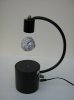
I had a chance to play with the circuit a little more and found the magnet can get the wobbles up and then becomes more insensate as the wobbles increase, to the point the magnet moves outside the sensor area and falls off.

By adding some feed back to the opamp helps reduce this effect.
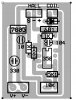
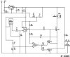
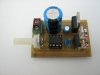
I added 100:1 feed back, see schematic for R4 and R5, also added a 5 volt regulator and a diode across the coil to the schematic.

I have since changed the circuit even further and have added a 08M picaxe to my board, the only function the picaxe do is to monitor the output of the opamp for pulses and if no pulses are detected in 50ms it turns the coil off.
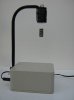
The reason for this is at times the magnet can wobble and fall out of levitation, and without the magnet near the sensor the coil switches full on, drawing a lot of current and over heats the voltage reg, the addition of the picaxe solves this.

It also allows for a lower resistance coil to be used as it is no longer limited by the voltage reg, as when the circuit is operating with PWM to the coil it draws 50-100ma, but without PWM it can go as high as 1-2 amps, the reg can handle this for 50ms.
When i have time i will draw up the schematic for the revised picaxe circuit also.

Pete.


Hello buddy
I've used this circuit.
I have in the conection winding 4.5 volts. But The coil not magnetive
Please help me
 

Attachments

  • schematic.JPG
    schematic.JPG
    49.4 KB · Views: 280
Status
Not open for further replies.

Latest threads

Back
Top