Continue to Site

Welcome to our site!

Electro Tech is an online community (with over 170,000 members) who enjoy talking about and building electronic circuits, projects and gadgets. To participate you need to register. Registration is free. Click here to register now.

  • Welcome to our site! Electro Tech is an online community (with over 170,000 members) who enjoy talking about and building electronic circuits, projects and gadgets. To participate you need to register. Registration is free. Click here to register now.

Need quick help on magnetic levitation circuit

Status
Not open for further replies.

RobertShin

New Member
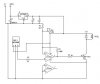
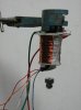
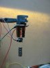
Hi there people. I'm currently doing a project to make a levitating system with the use of an electromagnet and a control circuit to vary the current in the electromagnet, thus getting the object to levitate. The sensor I'm using is UGN3503 hall effect sensor, and this measures the change in magnetic flux and gives and output voltage proportional to the change. This is fed into the TL494 chip, which then gives a PWM signal based on the error amplifier. This signal then goes to a power mosfet, which turns the electromagnet on and off.

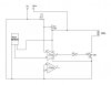
Here's what I've done:

Pin 1 - Hall effect output
Pin 2 - Reference voltage
Pin 3 - Left it open
Pin 4 - Left it open
Pin 5 - 220 nF Capacitor
Pin 6 - 2.7k Resistor
Pin 7 - Ground
Pin 8 - 12V supply
Pin 9 - Gate pin of a power mosfet
Pin 10 - Shorted to 9
Pin 11 - 12V supply
Pin 12 - 12V supply
Pin 13 - Ground
Pin 14 - Into pin 2
Pin 15 - Left it open
Pin 16 - Left it open

I am failing to get any PWM signals at all, what have I done wrong?

Here is the data sheet

http://www.datasheetcatalog.com/datasheets_pdf/T/L/4/9/TL494.shtml

Thanks
 
Last edited:
Funny enough i just built one for the hell of it, and after a few trials of methods its working fine.

First i tried using a micro, but that worked although it proved too slow in adjusting the coil on/off, so back to basics and used an op-amp, this works very well.

My recommendation to you is to scrap half the junk you have and go simple as i did, it works.

I used a LM-358 op-amp (or 1/2 of it) the non inverting input has a pot set as a voltage divider on it so the threshold can be adjusted, the output from the hall sensor is fed into the inverting input of the op-amp, the output of the op-amp supplies the base of a BD681 transistor via a 1k resistor, the transistor drives the coil.

All very simple and the circuit operates off 5 volts, dead easy and works well.

Excuse the rough setup in the photos as this was just proof of concept

Pete.
 

Attachments

  • 011 small.jpg
    011 small.jpg
    39.9 KB · Views: 2,259
  • 016 small.jpg
    016 small.jpg
    42.2 KB · Views: 2,276
Are you using a power transistor?
I think that just might be the prime component that was required for my circuit to work.
 
Last edited:
The transistor is a darlington rated to 4 amps but the circuit draws less than 100mA in my case.

Here is the schematic for the circuit i done...........

Pete.
 

Attachments

  • Levitation device.JPG
    Levitation device.JPG
    31.6 KB · Views: 2,862
For anyone interested the wave form of the circuit with a magnet in levitation is as per the photo below, the volts is set to 1v/cm and 1mS/cm.

No emf diode used.

Pete.
 

Attachments

  • 003 small.jpg
    003 small.jpg
    45.7 KB · Views: 806
Nice! Thanks for the scope trace. It looks to be running a fraction over 3kHz once it settles down. Is that trace the output of the LM358?

I'd be tempted to put a cap in there somewhere and get it to oscillate a little slower and more stable.

What is the hall sensor number?

Good work too by the way! :)
 
If interested, here is a Google patents link of a magnetic levitator for XY positioning using conical coils in a cross-pattern...

**broken link removed**
 
Lurkingdevil - I haven't actually put my transistor into the circuit yet, but I thought that would have been unnecessary for the output pin of the PWM chip to actually give an output at all.

Pete - Ok that's awesome, I'm guessing you've used a UGN3503 Hall Effect? I might give that a go too just to show the principle of levitation, but for future studies I would still like to try a PWM, and possibly a programmable microcontroller as well. Anyway here is the schematic I'm using, and the boxed part is the part I haven't connected yet. I'm just testing the output pin 9 & 10 compared to ground, but I never seem to get a PWM no matter what I do to the input voltage at pin 1. Any ideas why?

The pot. going into pin 2 is for height control, trying to levitate it at different distances from the electromagnet.
 

Attachments

  • Levitator.png
    Levitator.png
    14.8 KB · Views: 5,064
The trace was from the output of the LM-358, and the hall sensor was a UGN3503U, but i think any linear hall sensor should work.


I dont see why you have a led across the coil as at 3khz do you think you will see it flash??????

I think the supply voltage might be too high as the coil will be too powerfull, requiring the magnet to be further away, then you have the problem of the magnet being too far away from the hall sensor to read, so you endup in a loop of things not working, try 5 volt supply.

The reason i post schematics is for all to use and to share the information, so of course you can use it.

I really dont care what chips you use, for your final project, my only aim was to show how simple this can be to get it to work, as all those who try a fancy design come here asking why it wont work.
As i said i too tried a micro and other design ideas, but the best result was back to basics and keep it simple.

Pete.
 
The LED was placed just to make sure current was passing through it, which didn't happen so I knew something wasn't working.

I'm wandering, is the hall effect readings in any way altered by the changing magnetic flux of the electromagnet itself? As the sensor will be stuck on to the electromagnet. And because it's using attraction rather than repulsion, the levitating object doesn't necessarily have to be a magnet does it, just as long as the object is paramagnetic? Or would that be too weak.
 
Are you aware the hall sensor must be faced the correct way to the coil, in my case the flat side (or back) of the hall sensor faces the coil.

With a 5 volt supply to the hall sensor, the sensor output should be somewhere around 2.5 volts, and as you bring a magnet towards the sensor the output voltage should increase, it might pay for you to check this with a meter.

It is also important which way the coil is connected so the right magnetic polarity is created for the hall sensor, if the coil wiring is reversed than the sensor will decrease in its output voltage when the magnet is moved near the sensor.

I have had not very good results with using a metal object in place of the magnet as the change in field strength is too weak for the hall sensor and the object gets too close to the coil.

I built a PCB today for the circuit and added a 20 volt zener across the coil (in reverse) this has cleaned the wave on the cro up greatly and has made not ill effects to operation.

Pete.
 
I assume the right polarity of the electromagnet for the hall effect sensor is the pole that attracts a magnet that has a pole facing the hall effect so that it increases the output voltage? If you can make sense of that....

oh ok but if it's something like iron which will magnify the magnetic field, it's possible?

what is the resistance of your coil?
 
One coil i wound has a resistance of 21 ohms and a second coil i wound has a resistance of 13 ohms, either coil works just as well as the other.

Pete.
 
One thing to remember with the coil ohms is the current it will draw, so one needs to consider what the power supply will handle.

Lets use my circuit for an example.
I have a LM-7805 v reg for the 5 volt supply and rather than use a big heat sink on the reg to drive it up to 1 amp output i wanted the maximum current drawn by the circuit to be less than 500mA.

When the magnet is in levitation the circuit draws 50-100mA, but if the magnet falls away the coil will switch hard on, untill a magnet come back into the sensor range.

So with ohms law we can work out our coil ohms limit

5v / 0.5A = 10 ohms

250 mA is more than enough for me so i went to more turns on the coil and increased the resistance to around the 20 ohm point.

You could add a resistor in series with the coil to reduce the maximum power drawn but more turns on the coil will give better magnet strength in the coil and increase the resistance.

You guys have been trying to drive your coils with 12 volts and the power consumption goes up much greater

12v / 10 ohm = 1.2 amps

Also the coil will generate a fair bit of heat at this current, and may fail in time.

Pete.
 
4k7 is a standard way of writing a resistor value and means the same as 4.7k
 
I had a chance to play with the circuit a little more and found the magnet can get the wobbles up and then becomes more insensate as the wobbles increase, to the point the magnet moves outside the sensor area and falls off.

By adding some feed back to the opamp helps reduce this effect.
I added 100:1 feed back, see schematic for R4 and R5, also added a 5 volt regulator and a diode across the coil to the schematic.

I have since changed the circuit even further and have added a 08M picaxe to my board, the only function the picaxe do is to monitor the output of the opamp for pulses and if no pulses are detected in 50ms it turns the coil off.
The reason for this is at times the magnet can wobble and fall out of levitation, and without the magnet near the sensor the coil switches full on, drawing a lot of current and over heats the voltage reg, the addition of the picaxe solves this.

It also allows for a lower resistance coil to be used as it is no longer limited by the voltage reg, as when the circuit is operating with PWM to the coil it draws 50-100ma, but without PWM it can go as high as 1-2 amps, the reg can handle this for 50ms.
When i have time i will draw up the schematic for the revised picaxe circuit also.

Pete.
 

Attachments

  • Levitation device.JPG
    Levitation device.JPG
    28.5 KB · Views: 1,300
Last edited:
Status
Not open for further replies.

Latest threads

Back
Top