1. I learned about self-resonance which is the point where the inductor is not an inductor any more.
2. Way back when in ETO and other websites, there was a request to replace an automotive inductive vacuum sensor in a vintage vehicle. with something modern. The diaphram cracks and availability of a replacement sensor was near nill.
3. Knowing very little, I managed to create a current controlled inductor in the "right range" of inductance
and possibly the right frequency range that it's used by the ECM. Ballpark numbers I worked with was 65 to 125 kHz which I now don't believe. I had roll off problems at 100 kHz because of toroid characteristics and didn't know anout fr. I believe (7 YO memory) I could measure an L at 100 khz, but it was lower than at 10 kHz.
4. The frequency dependence of the sensor was not known at the time. It is now known to be ~82 kHz based on this thread and some measurements on a real sensor.
5. Some "other person" made an ersatz replacement device which made no improvement in vehicle performance,
5a. He had a good sensor and ECM on the bench. Sensors were $300-$400 then.
5b The OEM sensors have not been made in a long time.
5c. Elevation difference between me and the car that started it all is about 5000 feet. 250 vs 5000 ft. above sea level.
5e. I saw a used tested sensor on ebay relatively cheap recently, so I grabbed it.
6. I never got a good sensor to reverse engineer. I don't think anybody else thought it was necessary.
7. I disagreed with everybody on what the sensor measures. It cannot be absolute pressure because there is a port open to the atmosphere. So, I believe It's a 1 bar or 100 kPa vacuum sensor that measures "units" proportional to gauge vacuum..
8. I need some "on the car measurements", now I know what's needed.:
8a Frequency (@ 3 points)
8b AC waveform @ 3 points
8c Vacuum/ratiometric voltage from a "T"ed electronic ratiometric sensor in the same vacuum line (@ 3 points)
8d DC voltage across sensor and polarity (@ 3 points)
[Essentially a scope picture from a $20.00 USD DSO150 scope should work]
[the 3 points selected are values measured when trouble-shooting]
[Essentially: @idle (RPM only), @part load (a fixed man-made vacuum data point and RPM) and
Full load (disconnected vacuum line and RPM). All have expected vacuum advance values and tolerances. I need electronic sensor values coresponding to vacuum and inductance vs vacuum using the vacuum sensor. Max L is expected to be 3.6 mH.
8d. DC Resistance (50-60 ohms) and Vcc (Vacuum sensors are ratiometric)
8e. One has to assume the inductance vs vacuum transfer function of the OEM sensor is linear dictated by mechanical design.
9. The ECM ultimately creates a specific spark advance at specific RPM's and gauge vacuum values
9a. Presumably this has a marketable affect on driveability and fuel economy.
9a. The ECM knows about WOT (Wide Open Throttle) and idle via physical switches.
10. Need inductance at these data points in (#8). Need to measure the inductance vs vacuum transfer function.
11. The electronic sensor needs to have an isolating media and I found a single sensor that does today. I was "planning" to use two GM MAP s sensors initially.
12. A replacement sensor might not be plug and play.
11. Need to derive control current vs inductance transfer function.
11a. One particular core property that I need to exploit has like a +-30% variation - not good.
11b. If there is a DC current, it will add or subtract from the required control current, so polarity is needed.
11c. I need to find fr of my saturable reactors.
11d. Probably want the system to operate with Vbatt >= 8V. I don't think I have that right now..
11e. Control voltage compliance should probably be <=5V.
12. Don't know max inductance. It was estimated by another person from a leaky sensor.
12a. Ideally measured from a hand vacuum pump and electronic sensor.
12b. I could estimate by putting the sensor on a full vacuum port at idle on any vehicle and measuring.
13. Does the saturable reactor (wound inductor with a control winding) need slow-start to avoid voltage spikes?
14. Anything I did or bought was my choice,
15. Presumably as a "Litmus test", an electronic inductor can be quickly created for the two values and the amount of vacuum advance compared to nominal values.
16. Hard part is winding a toroid with that +-30% variqbility.
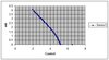
Attached is a graph showing the linearity over the expected range of L. I don't know fr and I don't know f. I know the control voltage compliance is probbably > 5V. I had a hard drive crash and it was about 7 years ago. I don't know what I have to re-create.