Continue to Site

Welcome to our site!

Electro Tech is an online community (with over 170,000 members) who enjoy talking about and building electronic circuits, projects and gadgets. To participate you need to register. Registration is free. Click here to register now.

  • Welcome to our site! Electro Tech is an online community (with over 170,000 members) who enjoy talking about and building electronic circuits, projects and gadgets. To participate you need to register. Registration is free. Click here to register now.

Need help with this circuit.

The graph of p-p output voltage vs supply voltage and load shows that an LM386 amplifier has a low maximum output current. When bridged with an 8 ohms load, each LM386 is driving the same current as in a 4 ohm load. The high 12V supply in post #9 makes it worse.

Each LM386 has a p-p output of 10V with a 12V supply and a 16 ohms load but the output drops to only 3.5V with a 4 ohms load. The output into 4 ohms is the same when the supply is from 8V to 12V instead of normally increasing the p-p level by 50%.

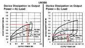
The graph of output power and heating shows that each LM386 powered from 9V and driving an 8 ohm load produces an output of 0.52W and heats with 0.52W. But an LM386 powered from 12V and driving a 4 ohm load produces an output of only 0.28W and heats with 1.2W.
 

Attachments

  • LM386.png
    LM386.png
    92.1 KB · Views: 111
Certainly true but I really doubt it will matter much in this application. Especially with relatively high RDSon transistors.

But I like the flyback diode solution proposed by Tony
I do not see any FETs.

The diode is mandatory to prevent exceeding Vceo.
 
I forgot that this thread was about a boo, bee, boo, bee squarewave screamer, not a hifi audio amplifier.
 
This method takes advantage of the 1kHz output from the 555 to drive a "X4 Dickson Charge Pump" to drive an 8 Ohm speaker with +/-26 Volts.

- Make sure your speaker can handle 100 Watts or more.
- The PNP and NPN drive transistors for the charge pump and output stage should ALL be rated for at least 10 Amps.
- The charge pump diode chain should be rated for at least 10 Amps as well.

Here is a Falsted Schematic Simulation I put together.


Here is a Dickson Charge pump I built some time ago to drive a motor using MOSFETs, instead of BJT's but the concept is all the same.
 
Multiple solutions exist, and the choice depends on the battery voltage and speaker power rating.

Beau Schwabe has a useful simulation, but the Dickson charge pump design has some significant drawbacks due to impedance transformations when driving all the 3.3mF capacitors. One issue is the insufficient base current at hFE when saturated, which requires manual adjustments in Falstad. Additionally, the boost voltage drops by 50%.
The reason for adding a series resistor to the speaker is to reduce the DC current that offsets the coil into the weaker part of the magnet.

However, I opted to add a power diode instead to create a flyback effect and achieve a higher AC voltage and less DC across the coil. The acoustic power is determined by the resistor across the coil and the series resistance (DCR) which generates heat and varies with the power rating of the 8-ohm speaker. For larger power-rated speakers, the DCR decreases, resulting in increased acoustic power ranging from 4 to 6 ohms out of a total of 8 ohms.

To further clarify, measure the DCR using a digital multimeter (DMM) and compare it with the impedance rating of the speaker for educational purposes. You can use either an N-channel MOSFET (Nch FET) on the low side or the 2N3055, a popular NPN power transistor from the 1960s. When saturated at 4A, the 2N3055 has a worst-case specification of 1.5V maximum, which translates to an Rce value of 1.5/4 = 375 mΩ. This value is significantly higher than that of a good power N-channel MOSFET.


1685147338955.png


See my simulated design using the flyback diode with 3 Li Ions for almost 12V or 4 if you prefer more power or 2 cells for less power.

1685148829060.png
 
Last edited:
Certainly true but I really doubt it will matter much in this application. Especially with relatively high RDSon transistors.

But I like the flyback diode solution proposed by Tony
The flyback diode avoids the shoot thru crossover currents and produces the most bang for the buck in making a low (~ 2 Ohm or Rb/hFE) non-linear output impedance noise maker. With the CMOS circuit you can make 4 oscillators in one chip. and with a HEX inverter maker 6. The CMOS output impedance is high on the 4000 series in order to handle 18V but the 74LS series are low impedance llke 50 Ohms (+/-50-%) but limited to 5.6V.
 

Latest threads

New Articles From Microcontroller Tips

Back
Top