Continue to Site

Welcome to our site!

Electro Tech is an online community (with over 170,000 members) who enjoy talking about and building electronic circuits, projects and gadgets. To participate you need to register. Registration is free. Click here to register now.

  • Welcome to our site! Electro Tech is an online community (with over 170,000 members) who enjoy talking about and building electronic circuits, projects and gadgets. To participate you need to register. Registration is free. Click here to register now.

Need help with switching signals

Status
Not open for further replies.

drkidd22

Member
Hello,

I need some help with some signals coming off a microcontroller. I'll try to give a good description and draw something If I need to.

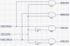
Basically I got two control signals coming out from a control source.
Each signal has to be shared by two different destinations.

So I got...

Control Signal 1: (Has two different destinations, destination A and destination B)

Control Signal 2: (Has two different destination, destination A1 and destination B1)

Both signals need to be simultaneously swapped by a single on/off switch. If Control Signal 1 is at destination A then Control Signal 2 must be at destination A1 as well.

Not sure if this makes sense, but I will draw something up if no one understands what I'm trying to do. I will be using a CPLD, transistor or whatever I may need.
 
Last edited:
An HCF4555 perhaps?
 
yes, that might do the trick I think.
I started doing the logic by hand and had something similar.
PWM signal is what I will be using.
 
So this is what I really want to do. If you look at the circuit logic it uses MOD_CNTRL as an input (switch) to simultaneously switch signals going out. I don't have the components yet to make the actual circuit but it works on the simulation. I will be putting in a 62Hz signal with 5ms pulse width at the two inputs, the inputs have a max peak voltage of 3.25volts. I want to know if anyone has done something like this before or if there are other suggestion that can help make a good circuit or even make this one simpler.
 

Attachments

  • logicCircuit.JPG
    logicCircuit.JPG
    102 KB · Views: 157
Last edited:
I'm not clear how this is supposed to work. Consider the Elev_Thr_In signal. If it is routed by the Mod_Ctrl signal to Elev_Out then nothing is going to Thr_Out and you will have an unknown situation there (loss of PWM control of the Thr_ load). Likewise for the other outputs.
 
Yes, that is exactly the point. To only enable one output at a time and disable the other. So control (route if you will) the output using Mod_Ctrl to either be at only ELEV_OUT or THR_OUT, depending on logic state of Mod_Ctrl.
 
I understand your point exactly. But what is happening to the ELEV (elevator?) when there is nothing controlling it? Is the ELEV unit happy with no signal going to it? If the setup is for standard modellers servos which expect a variable-width pulse at ~20mS intervals then it should be fine. But if it's for, say, continous speed control of a motor then it could lead to unwanted speed jittering.
 
Yes, it seems to be happy (with no signal it doesn't do anything) as expected therefore only the THR_OUT works when MOD_CNTRL is low.
So the main Idea for me is to have (THR_OUT and STEE_OUT) working, then if I flip the switch (MOD_CNTRL) to change logic then only (ELEV_OUT and RUDD_OUT) work.
This way I can switch my controls with a single flip of a switch to control other things.
It is for modeler servos.
 
Last edited:
Then the 4555 should do it.
 
I'm not sure those parts "pass" the signal. Your and gates should work. You can eliminate one inverter by using the output of 1 inverter to gate both AND blocks. If this is your 3.15 volt signal use the 74HCT series.
 
Yup, it is the 3.15 signal. I did test the gates and they work. I'm trying to simplify and try to use just one IC instead of two. Maybe I can find an IC with mixed gates. Thanks for the tip on the inverter.

I got a CPLD from Xilinx. I will give that a shot. Then I could prob have everything in just one IC?
 
Last edited:
You just need to be careful that your 3 volt signal will always be high enough to switch the logic you choose. (I'm assuming a 5 volt supply for Vcc?)
 
Status
Not open for further replies.

Latest threads

New Articles From Microcontroller Tips

Back
Top