Hey. I like looking at alternate solutions and there is no harm in doing so. My MOA is generally always look at all options,no matter how absurd and then star taking them apart.
A lot can be learned in doing so.
So, you probably don't have class II data to even look at and the BCM probably controls the dash.
So, maybe abandoning the "snooping" is a good idea.
I have an idea that's pretty easy and probably about $5 and uses one part. OK, a few parts. Make your switch DPST rather than a simple SPST (NO). Use the second circuit to operate one coil of a magnetic latching relay. So, when you push the button, the state stays forever, with and without power.
Then find a signal, like +12 when the car starter is turning and use that for the reset coil. So, a car start will cause tow/haul to go away.
You'll need diodes across the relay coils.
I picked an example part:
https://www.digikey.com/product-detail/en/TQ2-L2-12V/255-1008-5-ND
A dual-coil magnetic latching relay basically consists of a manet and a coil to "push" the contact. The transfer and hold magnetic fields are different, so removal of power keeps it in the stuck state, Both single and dual coils have polarity markings. They really don;t have to be followed, but a reverse polarity applied to the set winding would reset the relay. That's how a single coil relay works. One polarity sets and another resets.
The starter turning would be a nice signal that's +12 when starting and it goes away later.
Otherwise, there's a lot more involved with signal conditioning, power on reset, power protection and even isolation. A lot of electronic devices are uncomfortable having a signal applied to them when the power is off.
Make sense?
EDIT: This won;t work quite right, because all pushes turn it on and all starts turn it off. You need the pushes to toggle.
EDIT2: The ELM411
https://www.elmelectronics.com/ebench.html#Switches could do it. It can't drive a LAMP directly. It does need a 5V supply and it would be better to use a set of isolated switch contacts. The power choice would be from the ON side of the ignition.
A simple n-channel logic FET can be used for a LAMP/LED driver or a ULN2003/ULN2004 could be used depending if you wanted to drive the LED from the 12V or the 5V supply.

 . The SMT stuff? The comparator function? ....?
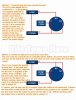
 .
..JPG")
.JPG")
