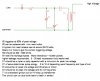
I recently come across a few old ignition coil lying around the house, so I decide to build a driver to use it to make arcs and etc. I started with the 555 based ones but obviously they are not giving enough power, so I moved on to off the line drivers, but my problem is that my SCR based design can only operate at line frenquency of 50Hz. which is to low to excite the coils fully. Can anyone offer me some sort of advice as to how to alter the frequency of an off the line ignition coil driver. or maybe a complete new design of a off the line ignition coil driver. Much appreciated.
I am using this design.
**broken link removed**
I am using this design.
**broken link removed**