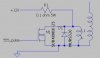
Sorry I did not label X2 its a diac or it can be a better quaity MOV with a good breakover voltage.
It can also be 1 or more mini noen glow bulbs in series. They have an additive breakover voltage,
Basicaly its just any device that will go from nonconducting to conducting at a specific voltage.
Two coils in reverse series is where you put the power in the + of one then connect - to - and take the power out the + on the second one.
Being the two coils are being driven 180 degrees out of phase from each other you get a much higher voltage differerntial at the HV outputs.
I built this circuit some time ago for a college science show day at the local college physics center.
I used two 6 volt ignition coils set up and driven this way. I placed them in an ice cream pail full of oil and called it "Bucket of Volts".

All you saw was a sealed plastic ice cream pail with two solid copper leads sticking through the lid. when you pressed a button on the drive box it would shoot 6 inch sparks between the two leads.


Scarred the crap out of the kids but they still kept pushing the button!
")
Being this is a highly inductive circuit you need the high voltage ratings to get any decent life out of it.
600 volt should work but it could still go give you problems when you draw the high voltage arcs out to a long lengh. Try it and find out!
A 1200v Scr is only a few dollars at digikey or any other online electronics parts supplier. Same with High voltage capacitors and diodes. If you know where to look this is a under $25 circuit to build. $50 if you need to buy the coils new.
But any ignition coil will work with this circuit. Even ones off lawn mowers!
")