Hi
I did a small project so i can improve my knowledge and skills on RF and PCB designing without the use of any specialized software.. but seems i'm getting no where since i can't make it work as it is supposed to be.
initially i had oscillation problems with the regulator... the voltage was wrong..i could measure ~1,65V and i couldn't easily catch the transmitting frequency on my radio and if i did probably it was only harmonics and i could hear a high pitch sound which it was shifting up and down if i was touching anything on the transmitter.
The regulators i tried were 2 different LDO that i had available
Reg102-A
Reg101-33
https://www.electro-tech-online.com/custompdfs/2009/07/reg101-a.pdf
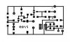
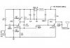
The problem persisted and i was thinking to try an LM2940-5 until i placed a ferrite bead in series with the (+) input power rail of the Reg101-33 and the problem i think is solved, the ferrite bead is a "Murata BLM31AJ601SN1L" which presents 600ohm impedance at 100 MHz and i had few available from past projects.
**broken link removed**
now i can measure 3.28V at the regulator output but still i can't manage to catch the transmitting frequency on my radio, for the LC tank i'm using an 100nH axial inductor so i can be sure that the inductance is somewhere near the needed value.
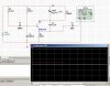
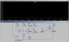
I also tried some simulations on Ltspice and multisim..but i didn't managed to make any succesful simulations..
I did a small project so i can improve my knowledge and skills on RF and PCB designing without the use of any specialized software.. but seems i'm getting no where since i can't make it work as it is supposed to be.
initially i had oscillation problems with the regulator... the voltage was wrong..i could measure ~1,65V and i couldn't easily catch the transmitting frequency on my radio and if i did probably it was only harmonics and i could hear a high pitch sound which it was shifting up and down if i was touching anything on the transmitter.
The regulators i tried were 2 different LDO that i had available
Reg102-A
Reg101-33
https://www.electro-tech-online.com/custompdfs/2009/07/reg101-a.pdf
The problem persisted and i was thinking to try an LM2940-5 until i placed a ferrite bead in series with the (+) input power rail of the Reg101-33 and the problem i think is solved, the ferrite bead is a "Murata BLM31AJ601SN1L" which presents 600ohm impedance at 100 MHz and i had few available from past projects.
**broken link removed**
now i can measure 3.28V at the regulator output but still i can't manage to catch the transmitting frequency on my radio, for the LC tank i'm using an 100nH axial inductor so i can be sure that the inductance is somewhere near the needed value.
I also tried some simulations on Ltspice and multisim..but i didn't managed to make any succesful simulations..
")