Continue to Site

Welcome to our site!

Electro Tech is an online community (with over 170,000 members) who enjoy talking about and building electronic circuits, projects and gadgets. To participate you need to register. Registration is free. Click here to register now.

  • Welcome to our site! Electro Tech is an online community (with over 170,000 members) who enjoy talking about and building electronic circuits, projects and gadgets. To participate you need to register. Registration is free. Click here to register now.

Need Help! PIC16F877A Port Initialization

Status
Not open for further replies.

Klitzie

New Member
I just want to ask how to correctly initialize a PORT in PIC16F877a cause its my first time using usually i used PIC16F84A due to more inputs a shift to pic16f877a but my problem is that i cannot correctly initialize PORTA of PIC16F877a due to the ADC function sharing with the port. Because i want to used my PORTA as an input for my sensors which i cannot distinguish either analog or digital.

Is the common sensor which is compose of IR and Phototransistor output an analog or digital signal?
 
Klitzie said:
I just want to ask how to correctly initialize a PORT in PIC16F877a cause its my first time using usually i used PIC16F84A due to more inputs a shift to pic16f877a but my problem is that i cannot correctly initialize PORTA of PIC16F877a due to the ADC function sharing with the port. Because i want to used my PORTA as an input for my sensors which i cannot distinguish either analog or digital.

The datasheet expalins it, or you could check my tutorials.

Is the common sensor which is compose of IR and Phototransistor output an analog or digital signal?

Usually digital.
 
If you look in the data sheet it has this code snippet to setup port A.
Code:
	BCF	STATUS,RP0
	BCF	STATUS,RP1	; Bank0
	CLRF	PORTA		; Initialize PORTA by
				; clearing output
				; data latches
	BSF	STATUS, RP0	; Select Bank 1
	MOVLW	0x06		; Configure all pins
	MOVWF	ADCON1		; as digital inputs
	MOVLW	0xCF		; Value used to
				; initialize data
				; direction
	MOVWF	TRISA		; Set RA<3:0> as inputs
				; RA<5:4> as outputs
				; TRISA<7:6>are always
				; read as '0'.

HTH

Mike.
 
Im using a pic-lite compiler it doing my program, im not good in assembly, can you convert this to a c code.
 
depends on which C compiler you're using, but for mine, I'd perhaps do:
PORTA = 0;
ADCON1 = 0x06;
TRISA = 0xCF;

(to convert the above assembly. I don't know if these particular values suit your needs, 0x06 and 0xCF, you'll have to figure that for yourself)
 
Also depends which pins you want to control the motor with. And yes, TRISA = 0x00; would make them all outputs, like I said, it depends on what you want to do, mine was just a translation of the ASM code.
 
The PIC has a lot of pins, which ones are you connecting the motor to? PORTA for example has up to 8 pins you could use, generally labelled RA0 to RA7
 
sorry for being late

but i should come back home first to obtain this information

DC geared motor tsukasa electric .CO made in japan
 
Before you can use your motor why don't you try animated stepper motor on proteus. This would help you to get a better knowladge about motors and also test your circuit and code.
 
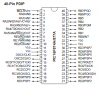
Hi. The PIC16F877A has RA0 to RA5, doesn't go to RA7, see attached pinout diagram. Here is a link to the data sheet:
https://www.electro-tech-online.com/custompdfs/2010/07/39582b.pdf
If you run motors from this you'll have to use the PIC to switch something like a transistor or driver chip, like the ULN2803A. The ULN chip has eight outputs, each capable of driving up to 500 mA, but not all at of them at once or the chip fries.
https://www.st.com/stonline/products/literature/ds/1536/uln2805a.pdf
This should be suitable for running small DC motors, even steppers. Servo motors can be driven directly from the PIC output pins. In all these situations you have to be sure to have adequate power to drive the motors without bringing the regulator's output so low that the PIC goes into brownout reset.
If you want to drive a DC motor both forwards and backwards you'll have to use a half-bridge circuit, usually built from FETs or ICs, like the L293.
https://www.st.com/stonline/books/pdf/docs/1328.pdf
This data sheet shows how to hook DC motors up in some different configurations.

And there are one-board solutions that do it all, like this Nano Driver Board:
**broken link removed**
This $25 board has a PIC16F88 18-pin controller as its brains. It has servo headers that can double as I/O, that is, analog (ADCs) or digital. It has all the parts above, including four FETs that can drive 9.2 Amps (!) _EACH_ !! And you have to purchase the $15 USB programmer at the same time. That's just $40 before shipping. Read the data sheet, available from the link above. One big plus is that this is a bootloader, with a free BASIC, so its as easy to use as you will ever find. Download the BASIC with its modern graphical IDE (Integrated Design Environment), check out the numerous demo codes for different motors, and you're off and running.
Hope that helped.
Take care.
kenjj
 

Attachments

  • PIC16F877A pinout.PNG
    PIC16F877A pinout.PNG
    29.5 KB · Views: 15,055
I have the same problem too. I use PIC 16f877A and choose PORTA as input of my switchs and have pull-up resistor 10K. So the default state of pins in PORTA is high or logic '1'. But when I use MPlab to write code ASM for my MCU, after I set trisc for PORTA as input, the state of PORTA is '00000000' that cause my switchs in PORTA are always in LOW that active state and my ciruit run automaticly as i press all that switchs.
I tried to set trisc PORTA as ouput first, initialize its state as '11111111' and set trisc PORTA as input. But value of PORTA is only changed to '01000000', that still cause wrong when I conplie and simulate in Proteus.
I tried to put my switchs to PORTC and try âgain. It has no problem as in PORTA, state of PORTC after I set trisc for PORTC as input is '11111111' that make my ciruit run exactly.
Can anyone explain and help me to solve that problem? Thanks.
My code is:
BANKSEL TRISA
CLRF TRISA
BANKSEL PORTA
MOVLW 0FF
MOVWF PORTA
BANSEL TRISA
MOVLW 0FF
MOVWF TRISA

value of PORTA and TRISA after my code is:
TRISA : 11111111
PORTA : 01000000
 
Last edited:
You need to turn off the analogue function. See post 3 of this thread for details.:rolleyes:

Mike.
 
Status
Not open for further replies.

Latest threads

New Articles From Microcontroller Tips

Back
Top