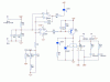
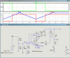
This circuit determines which voltage supply to switch to the motor - solar panel (SUN+) or power supply (24V+). My comparator circuit is toggling on/off when the +V IN is near the -V IN (6.5V). It cycles very fast.
Can anyone give advice on preventing the toggle? Circuit is attached.
Thanks in advance
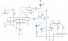
Can anyone give advice on preventing the toggle? Circuit is attached.
Thanks in advance
")