Electro Tech is an online community (with over 170,000 members) who enjoy talking about and building electronic circuits, projects and gadgets. To participate you need to register. Registration is free. Click here to register now.
Welcome to our site! Electro Tech is an online community (with over 170,000 members) who enjoy talking about and building electronic circuits, projects and gadgets. To participate you need to register. Registration is free. Click here to register now.
i need a circuit with 2 switches, so when you press switch A, LED A comes on and LED B goes off, then when you press switch B, LED B comes on and LED A goes off. whats the easiest way to make this?
i need a circuit with 2 switches, so when you press switch A, LED A comes on and LED B goes off, then when you press switch B, LED B comes on and LED A goes off. whats the easiest way to make this?
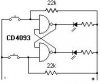
That's what bistables do, the one with the chip is actually identical to my suggestion using two transistors - both will light only one LED, when you press the other button it's LED will come on and the other LED will go off.
Yes, general purpose NPN transistors - nothing special at all, I'd normally use BC107's - but I use them for everything 8)
You could even use germanium transistors if you wanted!.
It's a very simple circuit to understand - all you need to know is that if you take the base of a transistor high, it's collector will be low. And if you take the base low, the collector will be high. Work from that, and follow the operation of the circuit!.
i cant get it to work. when i press button A, LED A comes on, press button B, LED B comes on, press both, both LED's come on. av tried it connected all different ways. what am i doing wrong?
i cant get it to work. when i press button A, LED A comes on, press button B, LED B comes on, press both, both LED's come on. av tried it connected all different ways. what am i doing wrong?
i have re-designed my circuit, so rather than have 2 buttons, i now have 1 which switches between mode A and B by pressing the same button... made this by usin an alternating on/off switch and making use of the extra gate to light the second LED. note that this is the unedited circuit.. if anyone wants an edited version post here and i will make it **broken link removed**
This site uses cookies to help personalise content, tailor your experience and to keep you logged in if you register.
By continuing to use this site, you are consenting to our use of cookies.