Continue to Site

Welcome to our site!

Electro Tech is an online community (with over 170,000 members) who enjoy talking about and building electronic circuits, projects and gadgets. To participate you need to register. Registration is free. Click here to register now.

  • Welcome to our site! Electro Tech is an online community (with over 170,000 members) who enjoy talking about and building electronic circuits, projects and gadgets. To participate you need to register. Registration is free. Click here to register now.

Need a small IC or circuit for SPI level translation (5V master to 3.3V devices)

Status
Not open for further replies.

iso9001

New Member
Hi,

I've been working with changing design requirements for an upcoming micro. There was need for an SPI eeprom of 64KB, that has since changed to 1MB+. The space on the pcb is really only going to allow for an soic-8 or smaller chip. I was going to use a 5V tolerant microchip part but they top out at 1Mbit. I've found an STM part that will work but its 3V max.

The 3V output from the rom is not enough to trigger the pic's input as High.

I've secured enough room for the chip, an sot-23 regulator and some level shifting.

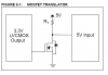
I've got two options, one is to use 3 small sot-23 mosfets that will each need a resistor to do the level shifting, the other option is to use an integrated level shifter.

I'm slightly concerned of the transition time using mosfets as the source resistor may cause problems at 10Mhz (or leak too much current at low level). Likewise a concern with the integrated translator is that I don't have a level shifter picked out and haven't so far seen a 3bit or 4bit that is small enough.


Recommendations ? Thanks
 
You could avoid the size problem by just making yourself a breakout board that would connect in the available space.
 
iso9001 said:
The 3V output from the rom is not enough to trigger the pic's input as High.

Are you absolutely sure about that?, it should (and always has for me) work fine, there are certainly plenty of other perfectly working examples as well.
 
Thats an odd question, but yea, last I checked a schmitt trigger input (CMOS level) VIH of 3.5V (.7 * 5VDD) is still higher then 3V.

Wait, let me double check.... 3.5V > 3V... yep, definitely :)


Now, thats going off of the datasheet. I have no idea if it would really work or not, datasheet says no, so thats what I'm inclined to go with.
 
Ambient said:
You could avoid the size problem by just making yourself a breakout board that would connect in the available space.

Won't fit in the enclosure then. Also, would have assembly issues with the mfg.... I've already pissed them off enough, I don't want to tell them we're now doing two pcbs.
 
Must the microcontroller run off 5 V for any particular reason? If the uC could be powered by the 3 V power supply, the SPI device could be easily interfaced to it.
 
eng1 said:
Must the microcontroller run off 5 V for any particular reason? If the uC could be powered by the 3 V supply, the SPI device could be easily interfaced to it.

One reason: 40Mhz (10*pll)

I'm going to be switching processors for all future projects. I'm running into too many limitations with the 18F lineup.
 
Then again, if the ST-CMOS listed in the datasheet isn't exactly giving a trigger point, rather its showing the effective voltage difference...

Where perhaps the pic would really be mid-rail at 1.75V ? That might make sense because the VIL is listed at 1.5V. If thats the case and judging by what you're saying Nigel from you're experience then maybe that will work.

I'm not sure on that. But, if the mid rail was 1/2 Vdd (2.5V) then technically, I should still be above it by a small margin at 3V. I wouldn't have much headroom above the rail but may have plenty to engage a switch below it.

I don't know enough about ST CMOS inputs I suppose. Thus the whole reason asking here first :)
 
iso9001 said:
One reason: 40Mhz (10*pll)

I'm going to be switching processors for all future projects. I'm running into too many limitations with the 18F lineup.
That's a limitation of the particular PIC you chose :) Take a look at the PIC18F45J10 family, 28/40/44 pin PICs that can run at 40 MHz @ 3 V. They have the MSSP.
Could they be suitable for your project? (I/O pins, package...)
 
Last edited:
Needs internal CAN, thats the main design req. 40Mhz is secondary.

I'm thinking of moving to STM ARM or Renesas chips. Pics are great, but I'm starting to find that I can only get this or that in a chip, at the same time almost always get ton of extra things I never use. Go figure.

There is the PIC24 lineup, but for the price and the package size (100pin tqfp) I might as well go to something a little more industry standard.


I'll look an see if there is anything I can move around in code to drop the clock down. If I'm more efficient with my code I may be able to get down to 20Mhz, but I'll have to check and see if thats within spec. Problem is then my stock of 10Mhz crystals from another project are useless and I'll have to order 20s or 5s. I doubt I could get all the time requirements within 10Mhz.
 
I have seen that, and the site it came from. I don't particularly like it thought.

Its more complicated then <attached> and for SPI (unidirectional) adds nothing for function. I'm not sure why the site that came from lists that for SPI when there is a much simpler solution.

(aside to Ambient, If I move around some caps and get really clever with the spacing and assembly I may be able to find a low enough profile header to make your idea work. Its not the most ideal solution but does allow me to get the design done and IF the customer ends up needing the extra memory I can address that at a later time, not ideal. But, it might work)
 

Attachments

  • Untitled-1.png
    Untitled-1.png
    70.1 KB · Views: 465
Papabravo: Those are some of the parts I came up with as well. I'm stubborn though and would prefer to find a signle soic8 or narrow so14 package that did 3 or 4 bits. In reality having 3 sot-23s is probably going to occupy the same amount of space, but I have a more confusing board layout with a more complex BOM and refdes. If I do find room for a daughter board I'll probably use that ON part.

Pommie: 4.3V is a good idea. I'm not sure how it would effect the rest of the 5V devices on the board (most importantly the CAN transceiver). That would allow me to receive data from the 3V rom, I would still need 2 level translators for MCLK and MSDO to knock the 4.3V down to 3V, CS would just be a 3V pullup the micro can ground. So that would save one more buffer. Stupid non-5V devices (Or when I transfer to a smaller die chip - Stupid high power 5V devices)... I've noticed my view on technology is really limited to how it effects ME at any given time :)


I need to check some header parts, hieghts, and get everything into my 3D model but I think I may have room for a daughterboard if its needed later. That would let me use a 1Mbit 5V rom now and then plan for later.

I'm not sure of the difference between using ON's translator vs a simple mosfet. Its probably just a predictable propagation delay and current usage. Since I'd probably just use a sot-23 mosfet there is no difference just using the ON part.

Cool. Now onto the endless jungle of headers on molex's and amp's sites.
 
Papabravo - Those are perfect! I know I should have kept looking but I've got tons of work to do on this schematic and its only a 50% chance I'll need the extra memory later so that has to get put on hold for right now.

But, a 3 banger soic-8 is sweet. I should have been searching more for lvttl buffers then level translators/shifters.

I'll be getting some of those ON parts asap for testing.
 
Glad to help. We gotta "cooperate to graduate".
 
........ ......... ........ You screwed me!!! j/k

Those aren't SOIC-8 they are US8. I didn't notice before :|

Oh well, I would think someone makes a pin compatible soic-8 version, I haven't found one yet, but I would think it exists.
 
Status
Not open for further replies.

Latest threads

New Articles From Microcontroller Tips

Back
Top