Continue to Site

Welcome to our site!

Electro Tech is an online community (with over 170,000 members) who enjoy talking about and building electronic circuits, projects and gadgets. To participate you need to register. Registration is free. Click here to register now.

  • Welcome to our site! Electro Tech is an online community (with over 170,000 members) who enjoy talking about and building electronic circuits, projects and gadgets. To participate you need to register. Registration is free. Click here to register now.

NE555 IR Repeater

Status
Not open for further replies.

Gayan Soyza

Active Member
I designed an IR Repeater using NE555.

The problem is without the Load (IR LED) its functioning.When I connect the load (IR LED) it will trigger all the time without a remote.In other words pin 4 is high when I connect the Load (IR).
 

Attachments

  • IR + 555.JPG
    IR + 555.JPG
    42.8 KB · Views: 604
Did you measure the collector voltage of T2 with and without output signal from the IR receiver?
 
... Results from a simulation on LTSpice:

The input which was used for this simulation was a 1 kHz frequency, with 100 µsec pulse width. ... Used 2N2222 instead of D400 transistor at the output. ... Used a visual LED instead of the IR version.

An interesting observation was that the C1 capacitor ... originally 0.001 µF ... appears to cause a sawtooth effect on the output current waveform of the circuit ... the current going through the output diode. The sawtooth amplitude of this waveform is about 50% of the total amplitude. This sawtooth waveform also has a higher sub-frequency, within the output pulse.

Could this particular event be related to your problem?

Changing the value of C1 to 0.1 µF appears to correct the output sawtooth deviation. The output is essentially a simple square wave ... following the input very closely.

... additional comment:
I think that the sawtooth waveform was actually observed at at pin 4 of the NE555. However, at the same time, there is an obvious abnormality in the current through the output LED. If you take an oscilloscope and probe pin 4 at a high enough resolution, you should be able to determine whether your original circuit has a similar defect.

NE555test.png
 
Last edited:
Thanks mates for your kind observation.

@ user_88
Changing C1 to 0.1 µF will make the frequency to 38hz which will never operate IR modules.The carrier needs to be 38Khz pulses.

@ Boncuk

I measured T2 collector voltage

With the IR module placed the voltage is 0V.
 
Last edited:
If it works without the IR emitter is it possible you have a feedback problem where the output IR is getting back into the input receiver? You could make the IR emitter an LED to see, or cover the receiver real good. They can be very sensitive.
 
Hi Gayan,

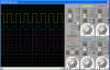
I have also simulated your circuit using a continuous input square signal of 38KHz at 4.8V output voltage from the simulated IR-receiver which is done using a function generator.

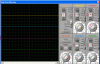
The output signal follows exactly the input signal as you can see by the scope screenshot.

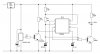
Extensive simulation shows the timer circuit runs as an astable multivibrator if the reset input voltage exceeds 1V (pretty precisely).

With the base of T2 floating this will be the case causing 1.3V at the collector which connects to the reset pin of the timer IC, hence not resetting it!

So you must force the base of T2 high enough to pull the reset pin low if there is no reception of the IR-receiver.

If you're using a series resistor with the power (+V) of the receiver just short it out and check what's going on.

Scope presentation: channel1 (yellow) -> input signal from receiver, channel2 (blue) -> signal at the base of T1, channel3 (violet) -> collector voltage of T1, channel4 (green) -> not used.

Next time I want to read "success". :D

Kind regards

Boncu
 

Attachments

  • IR-REPEATER.gif
    IR-REPEATER.gif
    10.4 KB · Views: 298
  • IR-REPEATER-SCOPE.gif
    IR-REPEATER-SCOPE.gif
    65.8 KB · Views: 205
  • IR-REPEATER-OFF.gif
    IR-REPEATER-OFF.gif
    10.4 KB · Views: 259
  • IR-REPEATER-SCOPE-OFF.gif
    IR-REPEATER-SCOPE-OFF.gif
    62.7 KB · Views: 188
Last edited:
Hi guys thanks for your input.I solved that load thing.Boncuk thanks for your extreme help.

I use these values.
R1 6.8K,R2=15K,C=.001 (102) In theory the frequency is 39KHz.But the scope shows almost half way mark 19KHz........

That's the latest problem.I also increased the supply to 9V Also generated 5V to TSOP1738.The circuit works but not in required frequency range.

I also notices there are some values it doesn't work with with NE555.
 
Last edited:
... from 555 Data Sheet

From one of the application circuit paragraphs:

"Adequate power supply bypassing is necessary to protect
associated circuitry. Minimum recommended is 0.1μF in parallel
with 1μF electrolytic"

... might be worth looking at.
 
Looking at the LM555 Data Sheet ... Figure 6 .... Free Running Frequency
It looks like the 0.001 µF capacitor is at the extreme range of the chart.

A few trial simulations produced an alternate set of values:
Ra=1.1k
Rb=1.3k
C=0.01 µF

Resulting in an approximate free running frequency of 38 kHz ...

... Something like 64% on duty cycle for these values.
 
Last edited:
Frequency won't Increase above 20KHz

I'm still struggling with this issue..

*That capacitor extreme range (0.001uF) can be a problem.
*The vero board (track board) can be another problem to add capacitance & cause to reduce the frequency.
 
Last edited:
Status
Not open for further replies.

Latest threads

Back
Top