Read about N-CHANNEL MOSFET’s. Gate and Base act as a capacitor; When gate reaches Threshold Voltage it allows current to flow from Drain to Source terminals by attracting negative charged electrons in between, constructing a conductive bridge.
It is easy to select two oposite charges on DC without major variations, however rectified AC waves, both have to variate in synchrony to keep a stable potential difference.
This shouldn’t go further with independent Base terminal MOSFETS, which could (theoretically) preserve its own potential difference with the Gate, from Drain and Source current. Nevertheless, common commercial ones comes mostly with Source and Base merged terminals.
Because capacitance variations transforms into D-S ohmic variations, Vds it is supposed to change quadratically(or so), being Vs = Vb, affecting capacitance bridge and creating acute waveforms.
From other perspective, DC Gate, DC Drain-Source MOSFETS circuit configurations also should be affected from smaller capacitance issues in the ohmic region, but they are used commonly that way anyway.
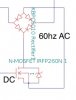
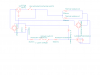
Explanatory attachment from a scheme where a DC current is applied to the Gate, while AC is passed through the D-S terminals.
¿What do you think will happen if this circuit is implemented?
It is easy to select two oposite charges on DC without major variations, however rectified AC waves, both have to variate in synchrony to keep a stable potential difference.
This shouldn’t go further with independent Base terminal MOSFETS, which could (theoretically) preserve its own potential difference with the Gate, from Drain and Source current. Nevertheless, common commercial ones comes mostly with Source and Base merged terminals.
Because capacitance variations transforms into D-S ohmic variations, Vds it is supposed to change quadratically(or so), being Vs = Vb, affecting capacitance bridge and creating acute waveforms.
From other perspective, DC Gate, DC Drain-Source MOSFETS circuit configurations also should be affected from smaller capacitance issues in the ohmic region, but they are used commonly that way anyway.
Explanatory attachment from a scheme where a DC current is applied to the Gate, while AC is passed through the D-S terminals.
¿What do you think will happen if this circuit is implemented?
 ), I didn't pay much attention to the specifications, or even if it was MOSFET or Thyristor? etc.