Continue to Site

Welcome to our site!

Electro Tech is an online community (with over 170,000 members) who enjoy talking about and building electronic circuits, projects and gadgets. To participate you need to register. Registration is free. Click here to register now.

  • Welcome to our site! Electro Tech is an online community (with over 170,000 members) who enjoy talking about and building electronic circuits, projects and gadgets. To participate you need to register. Registration is free. Click here to register now.

N-JFET

Status
Not open for further replies.
:lol: :lol: :lol: you would think so wouldnt ya :lol: :lol: :lol:
read this entire post, and youll see that i thought the same thing. Its just the opposite.

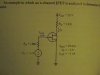
Audio, i have been fiddling around with a simulation to try and figure it out, and the only way that i can get it to work is to give the gate a negative voltage, but you said yourself that a negative voltage is not needed. How is this??

EDIT: I tried connecting the source to a voltage divider to give me half the supply voltage. This would mean that if the gate is connected to ground through a high resistance, the gate would be receiving a negative voltage relative to the source. Of course it didnt work on my simulator :roll: . Am i close though?

Severely confused i am
 
Ron H said:
williB said:
i just checked a motorola sheet for the same part..
it says the same thing..i dont get it?
an N channel Fet should turn on with a positive Vgs.
This is true of an N channel MOSFET, but positive Vgs on an N channel JFET will cause gate current to flow, which is generally not desirable.
thanks ! you know ,yall forced me to break out my book ..and i'll be dammed.
why they call it a N channel is beyond the scope of my concern :wink: :roll: ..
 
zach try this on the simulator..
 

Attachments

  • untitled_0058_0001.jpg
    untitled_0058_0001.jpg
    9.9 KB · Views: 486
I already did that willi and it worked :lol:

What im wondering now is how i can do it without havning a negative supply like audio mentioned.
 
ok how about another resistor under your JFET this will give you a negetive Vgs or you could use a regular N channel MOSFET :roll:
EDIT:: in the drain source path..
 
thats exactly what i was doing! it didnt work though.

I dont care what it is, jfet, mosfet, fet . . . I just want something that will turn off when a positive voltage is applied to its gate!
 
Wha??? I dont know where you are saying to put the resistor.
draw a diagram :lol:

goin 2 bed now so i wont be responding for a wile
 
The MPF102 is an N-channel depletion-mode Jfet. It requires its gate voltage be 0.5V to 8.0V negative to its source to be cutoff. It conducts fully between its drain and source when its gate voltage is the same as its source voltage. It is not a N-channel enhancement-mode Mosfet that is cutoff with zero gate voltage and is on with a positive gate voltage!

Zach,
A Jfet can be used as a linear amplifier with a source resistor to ground raising its source voltage to a few volts positive so that it conducts about half-way when its gate is grounded. When the gate voltage swings positive, the Jfet conducts more and raises its source voltage higher than its resting voltage. When the gate voltage swings negative, the source voltage will reduce nearly the same amount from its resting voltage, since it is a source-follower.

A PNP transistor with its emitter connected to +5V and a collector resistor to ground will turn-off when its base voltage is +5V. A low voltage fed through a resistor to its base will turn it on. :lol:
 
Status
Not open for further replies.

Latest threads

New Articles From Microcontroller Tips

Back
Top