Continue to Site

Welcome to our site!

Electro Tech is an online community (with over 170,000 members) who enjoy talking about and building electronic circuits, projects and gadgets. To participate you need to register. Registration is free. Click here to register now.

  • Welcome to our site! Electro Tech is an online community (with over 170,000 members) who enjoy talking about and building electronic circuits, projects and gadgets. To participate you need to register. Registration is free. Click here to register now.

Mysterious schematic symbol? TL494

Status
Not open for further replies.

MacIntoshCZ

Active Member
Hello,
I am wondering whats this symbol really means?
Its connected to oscillator and to reference pin in Op amp.
BTW why is there current source connected to ground?
Its like there is by default 0,12/ 0,7 V or higher due to pin 5 and 4?
Thanks
1597138910974.png
 
I would presume it's a pair of internal voltage references?, used to create the 'dead band' along with the comparators.

But why worry about what's inside the IC?, it's only a crude representation of what's there - and probably not at all accurate (there's no reason for it to be).
 
I would presume it's a pair of internal voltage references?, used to create the 'dead band' along with the comparators.

But why worry about what's inside the IC?, it's only a crude representation of what's there - and probably not at all accurate (there's no reason for it to be).
I always trying to figure out how it works from schematic. Thanks
 
How about using a chip designed for that?, the TL494 is a 1980's switch-mode PSU chip.
Can you please give me a example? I searched alot but i not found anything. Also i make a thread about it. No one reccomended me something. Thanks
 
Can you please give me a example?
What kind of a power supply are you building? input voltage, output voltage, power, isolated?

The LTC3721 is also old but at least it is designed to drive power MOSFETs not transistors.
1597154649554.png
 
The recommended output transistor current of the TL494 is only 200mA. That may not be enough to drive sufficient gate current for rapid switching of big IGBTs to avoid significant heating.
 
The recommended output transistor current of the TL494 is only 200mA. That may not be enough to drive sufficient gate current for rapid switching of big IGBTs to avoid significant heating.
I though that output from tl494 is only logic level for gate driver irf21864
 
The TL494 outputs are open collector and open emitter, so can be configured with external resistors to give whatever level you want (within reason!).
 
I use digikey.com but mouser and farrnel are good. This is a good choice because they work with almost all products.
In this case I know TI.com makes many power supply parts. Analog.com is a good place.

If you want half bridge, FairChild now OnSemi has FSFR parts.
1597179783002.png
 
the TL494 is a 1980's switch-mode PSU chip.
yet i still see them from time to time in new equipment... not much as i used to, but they're still using them.
 
yet i still see them from time to time in new equipment... not much as i used to, but they're still using them.

Certainly in domestic electronics they disappeared decades ago, and were replaced by more modern, more efficient, and (most of all) cheaper products. It's an antique, and requires a LOT of external circuitry to work.

I can't help thinking that anyone using them in new equipment has a seriously poor designer?.
Thanks anyone for help. NCP1396A is in our country quite costly, about 10$. Tl494 i bought cost me about 0.5$ but additional driver chip another 2.5$.
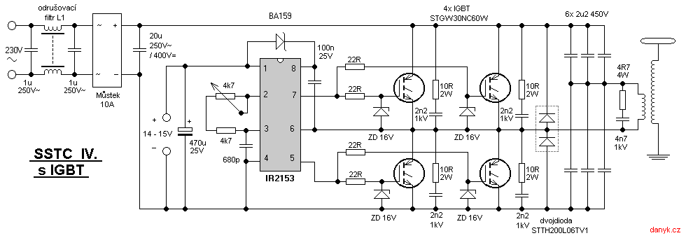
But i realized that danyk solution ( diodegonewild etc. He has a lot channels on YT) could work with adjusted capacitence. One pair of Caps ( 2x 1u) limits power to 317W (230V AC / 3khz).
*UPDATE
Actually when one transistor is open second capacitor is charging through load / second cap. Power should be higher than.
sstc4.png
 
Last edited:
I needed variable duty cycle and frequency.
I think the IR2153 is not good for duty cycle and frequency. It does not have a error amp.
It is a NE555 and a half bridge gate driver.
It should work well for a unregulated high voltage power supply.
1597236456412.png
 
Last edited:
Status
Not open for further replies.

Latest threads

New Articles From Microcontroller Tips

Back
Top