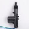
You are right, the actuators have no limit switch and yes I will used the translator
Better in terms of translation.
I don't know if here in Mauritius I will get the socket to buy it
Usually if you can get the relay, you can get the socket. It just gets messy wiring without one. Check with car alarm/stereo installers. they may know the relay as a Bosch automotive relay.
I want to lock/unlock all door
All can generally mean two (2) or four (4) doors So, 2 or 4 doors?
In any event, you will need one actuator per door lock mounted inside the door. Running the wires are usually troublesome. remember to use "drip loops" that prevent water from following the wire. If the relays are mounted base down, the wires hit a low point first and therefore the water doesn't end up at the relay terminal.
I have 1 actuator in my car, when I manually lock/unlock all door automatically lock/unlock form the driver door
OK, so you will also need a manual switch installed in the driver's door for lock/unlock?
A switch is easy. It would normally be a DPDT center off switch, momentary for each side., so (on)-none-(on) arrangement. The center terminals would go to ground and one Normally Open (NO) pole of the switch would go to orange/white and the other NO side would go to
orange (lock).
So from the back of the switch
L G x
x G U
G= ground
L = lock (orange)
U = unlock (orange/white)
===
You have a few choices:
Choice A (two relays per door installed in each door)
a) Install two relays in each door.
b) Install a source of +12 V (always on) in each door
c) Install ground in each door.
d) Install orange in each door - lock
e) install orange/white in each door - unlock
The driver's door would have access to everything and each door would get 4 wires. This keeps the wiring simpler.
Choice B (two relays, installed in driver;s door)
a) Install +12 (always on) in the driver's door
b) install ground in each door
d) Install orange in the driver's door - lock
e) install orange/white in the driver's door - unlock
f) Install another pair of wires out of the driver;s door connected to the motor.
So, you have six (6) wires out of the driver's door
g) the other doors only get two wires (pair f)
Choice C (two relays, installed in passenger compartment)
a) Install +12 always on to relays
b) Install ground to relays
c) All doors get 2 wires installed for the motor/actuator. All actuators are wired in parallel.
d) the driver's door needs 2 wires for the lock/unlock switch.
Some variations on this theme:
a) Put a lock/unlock switch on the passenger door.
b) Passenger door enable: In my case I had a Valet mode (parking garage mode) switch and a enable unlock from the alarm on the passenger side. I just thought it was safer to just unlock the driver's door most of the time. I did not have an interior lock/unlock button.
c) if more was known about the sink current of the alarm and the stall current of the motors/actuators, the relays could be eliminated, but I believe they need to stay,
d) The lock mechanism I installed used a huge solenoid.
e) With the manual switch for lock/unlock it's POSSIBLE to burn out an actuator by holding the button down for a very long time.
e1) A timer could be installed to prevent this (too complex)
e2) A properly sized polyswitch
https://www.digikey.com/product-sea...c-resettable-fuses/656272/page/3?k=polyswitch can be installed to prevent this from happening. This is typically done for window motors. Just this past summer, I had a power window not work because it was too hot outside.
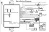
Les showed a diode across the coil of each of the relays. This should be a 200 V PRV diode or greater. A 1n4003 or bigger would work.
https://www.onsemi.com/pub_link/Collateral/1N4001-D.PDF The diodes are designed not to conduct in normal operation and to absorb the spike when the motor is turned off.
As you can see, the lock/unlock system is initially is totally independent of the alarm system. It just has to operate with a contact closure to ground for lock and unlock.
This is a lot to digest. The passenger doors may not have a way to run wires without water ingress.
It's a good idea to use 18 AWG or larger for wiring. Don;t ask me how I know.