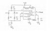
ok we have this astable multivibrator. My questions are :
1) How the inner RS Flip-Flop works inside the lm555
2)for what purpose is that Capacitor at pin5? How can i calculate its value for a circuit?
3)Pin 7 has a transistor which is connected at the output of the RS Flip-Flop. When is it working and when not?
4)When i want to have a DC%=50% what should i do?
thank you in advance!

") )
)

 ) but to exceed my knowledge in electronics.