Continue to Site

Welcome to our site!

Electro Tech is an online community (with over 170,000 members) who enjoy talking about and building electronic circuits, projects and gadgets. To participate you need to register. Registration is free. Click here to register now.

  • Welcome to our site! Electro Tech is an online community (with over 170,000 members) who enjoy talking about and building electronic circuits, projects and gadgets. To participate you need to register. Registration is free. Click here to register now.

multiple touch switch problem

Status
Not open for further replies.

sstimuluss

New Member
Hi, my first post here hope someone can help me out..

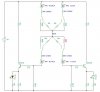
The circuit is simple: a touch connection current being amplified by a transistor to drive an LED.

I would like to have multiple independant touch controlled LED circuits (resistive not capacitive touch switches) Ie. two touch plates per LED, where the amount of pressure placed on the plates varies the brightness of the LED.

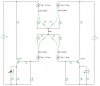
When there are two of these, such as in "Touch LED Circuit 1.jpg", the problem becomes that the two LED's can't be operated independantly of each other. (Because of the body being a common point).

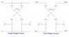
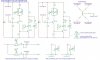
Can remedy this by using two voltage sources, as in "Touch LED Circuit 2.jpg", but this seems like overkill, as I eventually wish to have about 10 of these LEDs.

So is it possible to use one voltage source and somehow make those currents independant when more than one touch switch is closed?
 

Attachments

  • Touch LED Circuit 1.jpg
    Touch LED Circuit 1.jpg
    44.5 KB · Views: 305
  • Touch LED Circuit 2.jpg
    Touch LED Circuit 2.jpg
    48 KB · Views: 223
I don't think it's possible to build a pressure sensitive resistive switch, you could try a piezo transducer maybe.
 
Hero999 said:
I don't think it's possible to build a pressure sensitive resistive switch, you could try a piezo transducer maybe.

Thanks for reply, sorry my description was bad.

[edited this whole post for more clarity :]
I'm a musician developing a performance interface for dancers.
By pressure sensitivity I really meant contact surface area. So more contact -> less resistance
This also means that two dancers may touch each other to bridge a connection and vary resistance by how much contact they make.
I'm using large metal pads at the moment, but will be looking into other conductive material in the near future.
Also the metal pads are connected via fairly long wire to the circuit, meaning capacitance has been a problem. I seemed to have remedied this by placing 0.1uF caps between the transistor base and V+ and between base and V-

The LEDs are mounted inside small tubes facing LDRs, which are connected parallel to potentiometers of a MIDI interface (unfortunately dont have the time before the show to fully develop my own PIC-based interface, so have to make do with hacking a commercial one)

In my full circuit I'm also using the current driving the LEDs to further drive a transistor that turns an IR LED on with minimal touch contact. This IR LED is also mounted in a small tube facing an IR transistor which I use to close a MIDI note-on switch.

So with each pair of contact pads, touching them yields a Note-On with minimal touch, and further contact increases LED brightness/MIDI controller data.

I have a working prototype for one pair of pads using 9v DC, however to use more than one pair at the moment I have to use a seperate battery per pair.

Main problem is as follows with one voltage source:

skin contact is modelled as in my circuit diagram below, so a resistor between each contact point with a common centre point.

V+ is connected to Pad 1a and Pad 2a
Pad 1b is connected to base of T1 transistor
Pad 2b is connected to base of T2

Touching just Pad 1a and Pad 1b yields a certain resistance between V+ and T1 base. Now when Pad 2a and/or Pad 2b are touched, the current running between V+ and T1 base is also affected because of the common centre point in the skin resistor network.

With a seperate voltage source for each pad circuit, current isn't shared in this way.

How does one create this same independence with just one voltage source?

I could easily use a battery source for each pad, but I would rather use a 9vDC power supply to give a steady voltage.

hope this wasnt too long winded,any help is greatly appreciated!
 

Attachments

  • skin model.jpg
    skin model.jpg
    38.6 KB · Views: 187
Last edited:
here is a schematic of current working prototype

touching two pads lightly gives about 1mA in the controller LED, ranging up to 8.5mA with full contact. this gives acceptable range of resistance for LDR. Also, IR LED turns on full with minimal contact so that controller LED current may be varied widely once Note is turned on.

does anyone have any comments/suggestions? I would be very appreciative of feedback so that I can improve my simple design.
 

Attachments

  • 2 Note Touch Circuit.jpg
    2 Note Touch Circuit.jpg
    90.8 KB · Views: 230
Status
Not open for further replies.

Latest threads

New Articles From Microcontroller Tips

Back
Top