Continue to Site

Welcome to our site!

Electro Tech is an online community (with over 170,000 members) who enjoy talking about and building electronic circuits, projects and gadgets. To participate you need to register. Registration is free. Click here to register now.

  • Welcome to our site! Electro Tech is an online community (with over 170,000 members) who enjoy talking about and building electronic circuits, projects and gadgets. To participate you need to register. Registration is free. Click here to register now.

Multi-Pulse Sequencer using 555s

Status
Not open for further replies.

fishcurry

New Member
Hi all,

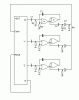
Basically, I need to make a series of pulses in continuos operation, five of them, with variable timing in between them. These pulses will be used in an electric stimulator (for physiotherapy) to act as push button presses. I've already created a "daisy-chained" circuit of monostable 555 timers with potentiometers to vary the timing, and an astable 555 timer hooked up to the first 555 to create the initial impulses. This is exactly what i'm doing:

**broken link removed**

However, I'm running into problems. If I make a pulse too short, then sometimes the pulse after it does not go. And, if I make the pulses too long, the astable timer seems to interfere. Basically, things aren't clear cut. To solve this problem, I am thinking about using something like this **broken link removed** . And hooking up the outputs all to one place. (I'm not creating a series of different pulses to diff locations, just one place).

What's the best way to tackle this problem? Continue with my 555's, try and play around with the 4017 circuit? I am also thinking about using a microcontroller to do this, although I would need to learn a lot about them. How easy is it to program a microcontroller for this function? Can it accept voltage level inputs to somehow vary the amount of time between outputs? I've just finished my first year of elec eng, and don't really know much about electric stuff besides gauss' law and the like...

Thanks, Arnold
 
This is rather wague method of generating pulses with different time intervals.

Instead, a better option would be to use 555 astable oscillator whose output is give to clock input of CD4017 which is a decade counter IC. The first output of 4017 will be 555 frequency / 1, second output will be 555 frequency / 2, third output will be 555 frequency / 3 and so on...
In this way you can take the output at different pins of 4017 to get desired time intervals between pulses. For connection between 555 and 4017 refer to this circuit:
https://www.electro-tech-online.com/threads/convert.360/
 
Sorry, I didn't make entirely clear exactly what I want...

I need to be able to adjust the timing intervals on the fly (as it's running). Basically what I am making is a timing device used to replace button presses for various parts of a person's gait cycle. I must be able to tailor the times on the spot for each individual. I have not seen this type of question asked before. What I have going can only work if the individual times of the monostable timers are less than the period of the astable vibrator. Think of a series of pulses, successively, and if you move the time for one pulse to complete (up and down voltages), the others will will "shift" down the timeline as well. And repeat....

I don't think that the 4017 thing will allow me to do it since the times are essentially set with OR gates. If a microcontroller can do this a lot easier, I wouldn't mind setting it up since I am just learning all this anyways. Would it be possible to adjust what I have? Somebody told me that flip-flops can be made to do this.... How would I use those?

Thanks, Arnold
 
Arnold, try this interstage network between your 555s. The trigger time constant is 11usec, and the recovery time constant is 1usec. It should recover in plenty of time. The diode allows the cap to recharge quickly on the positive edge, and the 1k resistor limits the current through the diode.
 

Attachments

  • interstage.gif
    interstage.gif
    4.2 KB · Views: 1,035
Pulse Sequencing

How about abandoning the 555s (the old-style ones take massive current spikes when they switch - 1/2 amp or so ...)

If you use a 4017 as the sequencer and trigger a monostable from each output you can alter each mono time. All the monostabs are diode-ANDed together to give the clock pulses for the 4017.
If you want less than the full 10 outputs simply diode the first spare output back into the reset input.

I have shown monostables formed from two 4001 'NOR' gates but the idea is the same if you stick with 555 timers.

The timing for each monostab is calculated as 0.5*R2*C2 (As I have labelled components) so a 1Meg variable resistor and a 33uF cap will give upto about 15 seconds.

R1 and C1 act as pulse shapers to give a short trigger to the monostab (maybe 22k and 0.1uF for a 1ms pulse?)

R3 and C3 act as pulse shapers for the monostab output (22k and 0.1uF again?)
D1 (one diode from each monostab) forms the AND gate and R4 (10k to 1Meg - doesn't matter!) just stops the AND gate's output floating when there is no pulse.

If you want just a single stream of pulses form a single output then you could use the clock line but the components suggested will make each pulse only 1mS long ... If the pulses are full-length from each mono then the output would be a constant DC anyway, maybe you want to control pulse ON and OFF times independently? (this will double the number of knobs to fiddle with though).
 

Attachments

  • Pulse-Sequencer.gif
    Pulse-Sequencer.gif
    5.5 KB · Views: 1,019
Well, after trying my circuit and reading at all your replies, I've come to the conclusion that the thing I have right now is the only thing that can allow me to adjust each time individually and not have overlapping sequences (If I adjust the time too long on the 4017 circuit this happens).

Thanks all.

Arnold
 
Confused

Whichever solution you use, I have one question ...
You say all the output pulses are going to a single output.

If all the seperate pulses are 'OR'ed together then won't you get a constant ligic '1' at the output? there seems to be nothing between these pulses to distinguish one from the other...
 
Status
Not open for further replies.

Latest threads

New Articles From Microcontroller Tips

Back
Top