Continue to Site

Welcome to our site!

Electro Tech is an online community (with over 170,000 members) who enjoy talking about and building electronic circuits, projects and gadgets. To participate you need to register. Registration is free. Click here to register now.

  • Welcome to our site! Electro Tech is an online community (with over 170,000 members) who enjoy talking about and building electronic circuits, projects and gadgets. To participate you need to register. Registration is free. Click here to register now.

MOV's operation.

Status
Not open for further replies.

alphacat

New Member
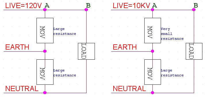
I read in how stuff works that:

"When voltage is too high, an MOV can conduct a lot of current to eliminate the extra voltage.
As soon as the extra current is diverted into the MOV and to ground, the voltage in the hot line returns to a normal level.
"

I'm not sure though why the extra voltage doesnt reach eventually to the appliance itself.
The reason that if V(A) equals 10KV, V(B) wouldn't reach 10KV, is due to the fact that the reflection coefficient in point A is:
Γ(A) = (0 - Zc) / (0 + Zc) = -1 ; (Zc is the characteristic impedance of the line)
and therefore the propogating voltage and the regressing voltage cancel each other?


movs-jpg.35751
 

Attachments

  • MOVs.jpg
    MOVs.jpg
    59.6 KB · Views: 1,197
The MOV will become a more like short when there is a voltage too high. Like a spark gap.

The current will split between the resistance from the MOV and the resistance formed by LOAD in series with the resistance between the Earth and Neutral.

Why are you using electromagnetics theory?
 
Thanks for the help.

According to what you're saying:

V(LOAD) = [ V(LIVE) - V(EARTH) ] / [ R(LOAD) + R(EARTH) ] =
= 10KV / [ R(LOAD) + R(EARTH) ] = Very large current.

If so, how does the MOV protect the appliance?

movs-jpg.35756
 

Attachments

  • MOVs.jpg
    MOVs.jpg
    64.4 KB · Views: 976
Ok.

Let's use the electrical circuit POV.

Rmov and Rearth are <1, lets assume 0.1 ohm .

R load >> 1, lets assume 9.9 ohms.

As you said, the total current is very large.

Rtotal = Rload + Rearth = 10 ohms

As 10 >> 0.1, Rtotal // Rmov =~ 0.1 .

So the Total Current =~ V/0.1 =~ 10*V Ampères.

Ok.
So you have V volts at the node and 10*V A entering the node.

But how much of this 10*V current will pass through the MOV?

Imov = V/0.1 = 10*V .

As I total =~ 10*V and Imov = 10*V

And we know that the sums of the currents entering the node is the sum of the currents leaving the node:

Iload =~ Itotal - Imov = ~10*V - 10*V =~ 0 Ampères (or nearly 0).

That means Iload << Itotal.
 
Hey, thanks again.

In your example:
R(LOAD) = 9.9Ω.
R(MOV) = 0.1Ω.
R(EARTH) = 0.1Ω.


The currents in the circuits are:
I(MOV) = 10KV / 0.1Ω = 100KA
I(LOAD) = 10KV / (9.9Ω + 0.1Ω) = 1KA

Indeed I(MOV) >> I(LOAD), but I(LOAD) is still very large and therefore is damaging the appliance.

Now without the MOV, we still receive:
I(LOAD) = 10KV / (9.9Ω + 0.1Ω) = 1KA.

So how does the MOV protect the appliance?
 
Last edited:
Ok.
Maybe the resistance for the MOV was too high.
In a datasheet, a MOV admits a transient of 1200 A with 0.65 W of dissipation (0.4 us). That would be ~ 0.5 micro ohms.

Redo the calculations and you are going to see.

A MOV when it is triggered acts like a spark gap, it becomes a short.

It is know that when a voltage supply is shorted, the voltage goes to 0V.
 
Redoing the calculation leaves us with:
I(MOV) = 10KV / 0.5µΩ = 20GA
I(LOAD) = 10KV / (9.9Ω + 0.1Ω) = 1KA

I(LOAD) hasnt changed and remained too high for an appliance to handle.

It is know that when a voltage supply is shorted, the voltage goes to 0V.
Why is it known?
I know that there's a voltage drop-out in the power supply's output when the current increases due to the source resistance of the PSU, but not that its output goes down to zero.
 
Last edited:
Alphacat, you used a voltage source with no series resistance. Add some series resistance to the voltage source and see what you get.
in a true short circuit, IE a 0 ohm connection the voltage goes to zero, in real world circuits this never occurs because EVERY portion of a circuit has a finite resistance regardless of how low it is. You have to keep in mind these series resistances and make sure you model ALL of these resistances properly or you'll get non-sensicle results like 20GA's of current being drawn. You can calculate the actual series resistance of your power supply by checking the no load voltage and the loaded voltage and determing the impedance that's there, but this doesn't work for switch mode power supplies.
 
Last edited:
There will never ever be 10KV across the MOV. The MOV will clamp at a much lower voltage (say 180V) and take the surge current (many many amps) until the voltage drops back down 180V.
 
There will never ever be 10KV across the MOV. The MOV will clamp at a much lower voltage (say 180V) and take the surge current (many many amps) until the voltage drops back down 180V.

Yes. After the voltage goes higher than, let's say 180V, it will act like a spark gap.
 
Alright thank you!
now I got you!

The reason that the voltage drops when the MOV's resistance gets very low, is due to the source resistance of the mains.

Thank you very much, its so good to realize that.
 
The real world is far far more complicated than the mathmatics show =)
 
Yes Indeed.
Though it was my mistake that i didnt take the source resistance into the mathemtical account.

I wanted to ask a related question please.
Is there any reason to use only one MOV in the following configuration?
relay-jpg.35800


If the source resistance is what counts, then i think it is not a good idea, since a large current drawn from the LIVE, which is shunted into the Neutral wire,
will cause R(EARTH) to have a large voltage dropout, so the voltage on the appliance remains high, isnt it?
 

Attachments

  • Relay.jpg
    Relay.jpg
    60.3 KB · Views: 674
Last edited:
Actually if you open some protection devices you are going to find a MOV between:

Live - Earth
Live - Neutral
Neutral - Earth

And let's not forget that you consider Neutral and Earth 0V. (For a monophasic connection)

Some resistances you are going to have:
* The Live resistance = low.
* The outlet Neutral -> transformer Neutral resistance = very low ~0
* The Neutral -> Earth resistance = low to very low (below 1 ohm)
* The wires resistances = low

The voltage dropout at Rearth would, indeed, be a very big problem if you had a poor grounding.

And do not forget that MOVs protect against transients surges not a long duration surge. If a long duration surge happens, your MOVs tend to blow up.

For example, to deal with that, some telephone line protection, specially in rural areas, use:
A spark gap -> To deal with voltages higher than 5 kV.
A MOV -> To deal with the remaining HV transients.
Fuses -> To deal with the high current surges.

So a MOV alone is not 100% efficient, you have to use it along with other components, and even with that, often in case of Lightning, nothing can be done.
 
Thank you very much for your great help! :)

Could you please elaborate how the Live-Neutral MOV helps shunting the high voltage from the appliance?
 
Think of:

Rsource10kV = 0.1 ohm
Rmov_on = 10 u ohms.
Rearth = 0.1 ohm
Rneutral = 1 m ohm
Rload = 10 ohms

The total current is:
Let 10 kV = V

It = V/[0.1 + 10u // 10 + 0.1//1m]
It = V/[0.1 + 10u + 1m] =~ 9.9 V

Voltage at load = It*[10u//10] =~ 9.9V*10u = 99uV

So, with V = 10,000 Volts, the voltage at load would be 0.99 volts.
 
Finally I understand it, wow its only thanks to you comrade!
Thank you :)

Currently my surge protector only contains 2 MOVs that are connected from Live/Neutral to Earth.
I thought of cases of buildings having no Earth wire (I heard that in Germany not all buildings have wall outlets with Earth connection), so connecting an extra MOV from Live to Neutral should do the job, right?
 
Last edited:
Status
Not open for further replies.

Latest threads

New Articles From Microcontroller Tips

Back
Top