Electro Tech is an online community (with over 170,000 members) who enjoy talking about and building electronic circuits, projects and gadgets. To participate you need to register. Registration is free. Click here to register now.
Welcome to our site! Electro Tech is an online community (with over 170,000 members) who enjoy talking about and building electronic circuits, projects and gadgets. To participate you need to register. Registration is free. Click here to register now.
No, but you can connect the pin to the net you want and then draw that net somewhere else.
Connect the net to the pin you want and end it a little ways out. Name it (name tool) and label it (label tool). Then start your net somewhere else. Name it the same and label it as well. Labeling just puts the text above the net line so it's not confusing.
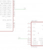
In the attached example I have named and labeled a net called TX which goes from one IC to another, but the green line doesn't physically connect them.
I usually avoid this myself out of personally preference. I like to just trace the lines wherever they go.
You could make the part with a separate symbol for each pin. Look at a quad AND gate for an example. Each gate is a symbol and the supply pins are a symbol.
You could make the part with a separate symbol for each pin. Look at a quad AND gate for an example. Each gate is a symbol and the supply pins are a symbol.
I think the "flags" you mentioned look a little cleaner and want to use them but i cant find anytyhing in Eagle which mentions flags and google searches are coming up empty too.
This site uses cookies to help personalise content, tailor your experience and to keep you logged in if you register.
By continuing to use this site, you are consenting to our use of cookies.

") I'm just curious what a schematic would like with a chip containing 100 pins, each carrying the device name and value.
I'm just curious what a schematic would like with a chip containing 100 pins, each carrying the device name and value.