Continue to Site

Welcome to our site!

Electro Tech is an online community (with over 170,000 members) who enjoy talking about and building electronic circuits, projects and gadgets. To participate you need to register. Registration is free. Click here to register now.

  • Welcome to our site! Electro Tech is an online community (with over 170,000 members) who enjoy talking about and building electronic circuits, projects and gadgets. To participate you need to register. Registration is free. Click here to register now.

Motorcycle CDI Pulse output

Status
Not open for further replies.

MaxD

New Member
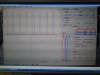
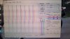
I am building a project where I need to simulate a single Charge/Trigger coil of an AC CDI.
My thinking is to convert a Hall sensor output to obtain pulses, both positive and negative, equal in size of around 400 volts, which will feed the original CDI.
The signal would originate from a Hall sensor output as a flywheel rotates, and must be synchronized with that flywheel.
Can anyone suggest suitable circuits to obtain this ?

I have a rudimentary knowledge of electronics, but not a good enough understanding to design this circuit/s.
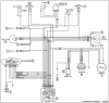
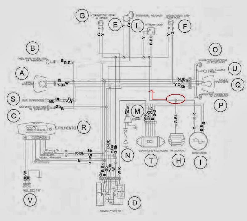
The purpose is to replace the single Charge/Trigger coil of a motorcycle CDI and there is no going back to the original setup.

Any help will be appreciated,

Many thanks in advance,

Regards Max.
 
Hi Max,

welcome to ETO.

We are getting quite a few new members from Oz and NZ lately. Which part are you from? If you put it next to 'Location' on your user page it will show in the box at the left of your posts.

If I understand you correctly, you have a motorcycle with a Capacitor Discharge Ignition (CDI), which is normally triggered by a 400V sine wave AC signal generated by a coil on the alternator [which is mounted on the engine crank shaft.]

Your problem is that the 400V AC signal is no longer available so you intend to derive an accurate trigger signal from the engine fly wheel.

Assuming all that is correct, I would think that a solution would be feasible from the electronic point of view, but the only problem that I can see is getting access to the flywheel and then attaching a small magnet reliably to the flywheel. The next problem would be to mount the sensor solidly in a position such that the magnetic field of the magnet impinges on the sensor as the flywheel rotates at high speed.

Just a few questions:
(1) What type of motorcycle do you have (some of us are mcyle nuts, so a picture would be nice)?
(2) Does the mcycle have a battery and, if so, is the battery 6V or 12V?
(3) Is the CDI custom or is it part of the motorcycle original fit?
(4) Do you have a circuit diagram of the CDI?
(5) How many cylinders does the mcycle have?
(6) Is the engine two stroke or four stroke?
(7) Does the mcycle have an electric start?
(8) Can you say exactly what the signal is that should connects to the CDI trigger input; is it a sine wave, or is it a single pulse (hopefully)?
(9) Can you access the CDI components or is the CDI sealed?

End of questions.:D

spec
 
Last edited:
Hi Max, welcome to ETO. Thank you and thank you for your quick reply Spec.
We are getting quite a few new members from Oz and NZ lately. Which part are you from? Perth, Western Australia If you put it next to 'Location' on your user page it will show in the box at the left of your posts.

If I understand you correctly, you have a motorcycle with a Capacitor Discharge Ignition (CDI), which is normally triggered by a 400V sine wave AC signal generated by a coil on the alternator [which is mounted on the engine crank shaft.]
Yes, correct, the original CDI is both charged (North pole magnet passing I believe) and triggered (South pole magnet) by an AC single coil excited by the flywheel.

Your problem is that the 400V AC signal is no longer available so you intend to derive an accurate trigger signal from the engine fly wheel.
Yep, no longer available, although it still has a flywheel, there are no magnets from the original design. The space is now an electric starter motor, which I have completed and works.

Assuming all that is correct, I would think that a solution would be feasible from the electronic point of view, but the only problem that I can see is getting access to the flywheel and then attaching a small magnet reliably to the flywheel. The next problem would be to mount the sensor solidly in a position such that the magnetic field of the magnet impinges on the sensor as the flywheel rotates at high speed.
My plan is to drill holes for and mount the Hall trigger magnets in the outer face of the flywheel. The Hall sensor can be attached to a bracket mounted inside the outer cover.

Just a few questions: (1) What type of motorcycle do you have (some of us are mcyle nuts, so a picture would be nice)? Husqvarna WR300. 2 Stroke.
(2) Does the mcycle have a battery and, if so, is the battery 6V or 12V? It will have a 6C Lipo, so around 22Volt.
(3) Is the CDI custom or is it part of the motorcycle original fit? CDI is original and I wish to keep it so I keep the original timing curve/power characteristics.
(4) Do you have a circuit diagram of the CDI? Unfortunately, no, but I’m hoping I should not really need it if I can imitate the AC signal to it.
(5) How many cylinders does the mcycle have? One. Its plenty. :D
(6) Is the engine two stroke or four stroke? Mighty 2 stroke.
(7) Does the mcycle have an electric start? This is what the whole project is about. It will have/does have now if I can get the ignition going again.
I should mention I still have a complete, original and working ignition system also, but it can not be used in conjunction with my mods.

(8) Can you say exactly what the signal is that should connects to the CDI trigger input; is it a sine wave, or is it a single pulse (hopefully)? Sine wave, measured with the engine running, somewhere between 2-3000 rpm, (no tacho, and didn’t think to calculate from the CRO)200 volts on one of the wires from the trigger coil to the CDI, and around 10 volts on the other side of the trigger coil, measured on the oscilloscope, but the shape of the second wave looks like it is maybe driving something. These voltages will obviously increase substantially with higher revs.
I will take some more measurements and hopefully post screen shots of the readings, both with the trigger coil open circuit and running the original CDI. I can do this using the lathe as a test mule.

(9) Can you access the CDI components or is the CDI sealed? The CDI is sealed

End of questions.

Thank you again Spec for any help you can provide. I have been doing lots of reading lately, but maybe I don't absorb info like I once did. Too many grey hairs perhaps.
 
Thanks Max,

An interesting project, and very helpful replies.

A mate and his missus emigrated to Bunbury four years ago; they love it there.:cool:

I am a bit confused about the 22V battery. A motorcycle normally has a 6V system or, more frequently on modern bikes, 12V. Does the motorcycle have an alternator? Does the CDI operate from 22V?

Drilling the flywheel and inserting a tiny magnet sounds like a good solid approach, which should provide an accurate pulse.

Sounds like you have extensive mechanical engineering expertise and equipment, so that allays any worries about fixing the magnet and sensor.

You mention magnets, rather than magnet, but a single cylinder two stroke only has one spark per revolution of the flywheel

You also mention a hall effect sensor. Are you wedded to hall effect, because there may be a better sensor for a motorcycle.

It is good news that you have the original trigger mechanism in a working condition. Yes, if you could post an image of the two wave forms going into the CD unit that would be a big help.

Husqvarna WR300: nice bike. Bet you have some fun on that.:cool:

spec

**broken link removed**
 
Last edited:
Husqvana WR300, 2012 schematic for reference attached below.
 

Attachments

  • 2016_10_31_Huskavana_WR300_2012_SCHEMATIC.png
    2016_10_31_Huskavana_WR300_2012_SCHEMATIC.png
    172.4 KB · Views: 4,068
I've found this isformation that gives us an idea of what is inside the CDI ignition module by Googleing "2 stroke CDI ignition system"

Link 1
Link 2
Link 3
It has confirmed that the high voltage supply must be switched off at some point of the revolution so that the SCR unlatches. This should give us a start with the design. I think two hall sensors will be required to keep the circuit simple. (It could probably be done with one but a phase locked loop would be requred to get the two trigger signals. One to charge the capacitor and the other to trigger the spark.

Les.
 
G'day guys, sorry I have not responded earlier, I haven't drowned. Busy with work.

Spec
: Originally the bike has no battery, it is powered by a single phase alternator, lights powered by AC, and the speedometer and horn by rectified/regulated DC. I have chosen a 22 volt Lipo battery for this mod. Battery charging will be worked out later, if required. It is really only used off-road and it still has a kick starter.
My choice is to fit two magnets for the Hall, I need a positive and negative pulse anyway, but also to keep flywheel balance. But not wedded to a Hall, just thought it might be most suitable.
I did some measurements last night with my old stand alone scope, not convinced of results. I want to re-run them again using 100x probe on the USB scope.
The wiring diagram above is for a 2012 model. The 2009 model circuit below has rudimentary shunt regulated AC driving the lights.
The S-B and B wires from the alternator are the Charge/Trigger coil output to the CDI.


You call that FUN, wide open throttle it's more like :wideyed: Yeah, love the bike, it goes like a cut cat and handles real well also. :)

Les, thank you for your reply. I had seen those links/circuits. I am very keen to keep the original CDI unit so as to keep the original 2 stroke timing curve. (not the same as 4 stroke)
Each of those links creates/uses a new CDI itself. Correct me if I am wrong, but those circuits would not imitate a single Charge/Trigger coil output, my original CDI is looking for.
Two halls would not be a problem to mount, but I understand there are analog Hall sensors giving positive and negative output, so they were my first thoughts .

Max.
 
Hi Max,
The idea of the information was that it suggested what was likely to be inside your existing CDI unit. I had wondered if the hive voltage could just be supplied by an inverter. As they seem to use an SCR the high voltage must be interrupted so the SCR does not latch up. You can get some hall effect gear tooth sensors that would not need a magnet fixed to the flywheel. They would just need a small groove machining on the rim or face of the flywheel. This is an **broken link removed**. This should be a **broken link removed**to the data sheet on the device.

Les.
 
Spec, I forgot to mention earlier, there are four magnets in the original flywheel, so it has a wasted spark at the bottom of the piston stroke. CDI fires twice per revolution of flywheel, but only needed at top of stroke. I would think it has four magnets primarily for the lighting generator system. None of that should affect what I'm trying to do though. My modified generator has plenty of output.

Max

Thanks Max,

spec
 
Les, Thank you for that info. They look good if it does not matter to much if the Halls are digital output. A groove would be a better arrangement, less rotating weight if nothing else.
I would expect there are analog Halls that operate using the same tech.

Max.
 
POST ISSUE 06 of 2016_11_16. Please see post #33

Hi Max and Les,

I am thinking about a single magnet and single sensor, which means that there will be no lost spark. The question is though: is the lost spark required, say for plug cleaning?

Below is an outline block diagram and circuits that I hope will do the job.

spec

2016_11_04_Iss1_ETO_HUS_CDI_TRIGGER_VER2 .jpg
 
Last edited:
Another question Max

Is the power for the ignition system to be taken from the 22V battery? The current will be around 2A.

spec
 
Another question: is there any reason why you have gone for a 22V electrical system rather than the more standard 12V system?

spec
 
Hi spec,
If you look at the third schematic (Labled Finalized design.) in link 3 of post #6 you will see that they use a 12 volt to 230 volt transformer to produce the pulse that would have come from the high voltage winding on the original system. The 12 volts to the primary is triggered from the sensor producing one cycle of AC which is half wave rectified to charge the capacitor. In that circuit they are continualy triggering the SCR. I think it would be better if the SCR was triggered from the second sensor. I like the idea of the synchronous step up converter as it saves having to switch of the high voltage after every spark to unlatch the SCR. This is assuming that Max's CDI unit uses an SCR. When I was searching the web I was looking for the internal schematic of that particular CDI unit.

Les.

Hi Les,

Yes, you are quite right. SCR latch-on is a hazard. I had envisaged inhibiting the 200V SMPS for a period sufficient for the SCR voltage to drop below its holding voltage.

The CD ignition systems that I designed, had a current sensing resistor in series with the SCR and, if there was any current detected, the 400V inverter was inhibited to prevent SCR latch on.

One consequence was that the inverter sounded like a chirping bird, which the users really liked.:)

spec

PS : In theory, the oscillation of the the ignition coil primary winding should turn the SCR off automatically, but there is always the daily one-in-a-million event that disproves the theory.
 
Last edited:
G'day guys, the battery will have to power the CDI, at least during the starting phase, but could be switched to generator supply after starting. But if so, the PSU will have to operate from around 10 volts, from memory, the low rpm output of the generator.
The choice of a 22v batt was worked out as a balance between power available to the starter, starter torque, final generator voltage, cable sizes and stator hand winding difficulty.
What you might call a good/lucky guess. :D Nah, it wasn't actually a guess.
However, the elec system when the engine is running will be 12 volts as original. At this point I see no reason not to use the original regulator.

Hopefully I can do that tonight.
 
Last edited:
Well, apologies for the poor quality pic. Had to take a photo of the computer screen to get it small enough for this site to accept.
Please see attached pic.
It is the trace of the charge coil voltage, one probe on each lead from the coil to the CDI unit. Ground lead connected to the engine case. Engine running at around 3500 rpm, calculated from the trace frequency. The probes were set to 10x . As you can see, looks like I mis-read previous measurements of the Charge Coil output voltage, over 1,000 on the blue trace, ( I'm guessing very high input impedance ) to whatever it goes to inside the CDI unit. So the red trace is probably being held low by charging the cdi capacitor.

About the lost spark question, I do not know the answer to that, but my guess is it is not needed for cleaning or any other purpose. I suspect it is just a remnant of needing the 4 magnets and three original coils for the original generator.
 

Attachments

  • Charge coil.JPG
    Charge coil.JPG
    142.9 KB · Views: 310
Hi Max,
I assume the red trace is the trigger pulse. What is the maximum and minimum speed that the engine runs at ? There is a free utility that I use to capture parts of the computer screen that should give better results than using a camera. It is called Gadwin Printscreen. This is a link to their website.
If you had a better image that was too large here is an**broken link removed**
http://www.gadwin.com/printscreen/
Les.
 
Last edited:
G'day Les, thank you for those links. Below are a couple of clearer pics of the traces. This is taken at just over 2000 rpm (trace frequency, remembering it has a wasted spark)
There is no Tacho, but a practical minimum would be somewhere from 1,000/1,500 rpm to a maximum of about 9/10,000 rpm.
I did learn that the original CDI/magneto will not spark until the rpm is somewhere between 217 and 432 rpm, the only speeds I was able to set on the lathe. Which means the kick starter is spinning the engine over at a similar rate. But at 432 rpm, it will jump about 8 mm at the high tension lead. At 2086 rpm, it will jump over 20mm. So creating some serious voltage going to the spark plug.

So you would expect that shape of signal and voltage level on the Blue trace to charge the CDI internal capacitor ?
Its actually over 2,000 volts, or am I mis-reading something.
If the Red is the trigger signal, what would you expect it is driving that would give that trace shape and hold the voltage down like that ?
Those two probe leads are connected to each end of the charge coil as the engine was running.
These were the original measurements I took. I could not get the stand alone scope or the USB scope to work correctly while running the system in the lathe. Getting weird readings on both, so whether its stray EMF's or earth issues, I don't know.

I downloaded the Gadwin program, but two attempts failed to get it working. Said something about not being a valid Win 32 file or something.
No problem .

Regards, Max.
 

Attachments

  • 20160620_182309 (Medium).jpg
    20160620_182309 (Medium).jpg
    258.7 KB · Views: 320
  • 20160620_182309 (Medium) (2).jpg
    20160620_182309 (Medium) (2).jpg
    258.7 KB · Views: 291
Status
Not open for further replies.

Latest threads

New Articles From Microcontroller Tips

Back
Top