Continue to Site

Welcome to our site!

Electro Tech is an online community (with over 170,000 members) who enjoy talking about and building electronic circuits, projects and gadgets. To participate you need to register. Registration is free. Click here to register now.

  • Welcome to our site! Electro Tech is an online community (with over 170,000 members) who enjoy talking about and building electronic circuits, projects and gadgets. To participate you need to register. Registration is free. Click here to register now.

Maximizing Alternator output/ Boosting rotor voltage?

Status
Not open for further replies.

bojiser

New Member
Hi All,

I recently found this <thread> and thought this might be a good crowd to help a poor sod do some electrical engineering.

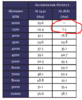
I am planning on using <this alternator> in a homebuilt airplane. It is meant for use with an external voltage regulator, and the company sells a 14V and 28V version. I noticed that running it at 28V produces basically zero power at idle (900 rpm at alternator) and almost twice the power at cruise rpm (3600 rpm at the alternator). Around 2200 engine rpm is where the 28V regulator starts to equal and then out-produce the 14V version.

So is there a way to optimize this, where the regulator would run at 14V during startup & idle, then be able to output maximum power during cruise? I know the first answer would be "use a more powerful alternator." But this one I linked is special because it is gear driven (no belt) and installs on the opposite side of the engine which is favorable for my CG.

So I think it would require a DIY voltage regulator. An arduino would monitor engine rpm and activate a boost converter so that the VR would modulate the rotor at 28V. I suppose my first question would be...does this make any sense to do? Would the voltage regulator still function properly when trying to output 14V? Would it be better to use a small secondary battery to supply 28V to the rotor?

I appreciate your patience trying to help/educate me!
 
Voltage is different than power. You can get dc/dc converters to convert nearly any input voltage to another output voltage. Even if an input voltage is changing within a range, a stable output voltage can be created or, for a given input voltage or RPM, you can likely step the output voltage to some desired value (assuming you have an arduino and ability to add some additional bits).
 
Lets see if I have this right. Your building an airplane yourself, and want to use a Lycoming or Continental engine in it, so from the little I know that means it will need to pass an FAA inspection since it isn't a ultra light with one of those. Do you think the inspector won't see or comment on you DIY regulator? Is your life or the life of others worth the $180 that the correct regulator/controller costs? I'm guessing you have more $ in the plane so far, why "cheap out" now?
 
.
 
shortbus= it's not a matter of cost, it's just me trying to maximize output. I only included the detail that this is for an airplane to help explain why I'm trying to use this alternator in particular. The extra output could be used for nice-to-haves like seat heaters, etc

gophert unfortunately I was unable to find a DC-DC converter of sufficient power rating on the output side. For example if I always run the alternator at 28V and want the bus voltage to be 13.5-15V and 60 Amps. At that high power, most have a 36V minimum input voltage and have a minimum order of 5 units or something.
 
I could run parallel DC-DC converters., they are heavy though.

Another option would be step-down transformers on each of the three phases on the stator prior to rectifying.

Coming at this from another direction, you might say that the problem is that the 28V option in the chart shown doesn't generate enough power at idle. Can someone explain why that happens?
 

Attachments

  • BC462-3H amps.PNG
    BC462-3H amps.PNG
    21.4 KB · Views: 387
the problem is that the 28V option in the chart shown doesn't generate enough power at idle.
It's not a choice of 14V / 28V _alternators_, there is only one alternator and they specify it for both 14V and 28V outputs, using different regulators.

At low RPM, it's simply not producing enough voltage to do anything useful for with a 28V system. eg. It may be capable of generating 22V at 2000RPM, enough for a decent output when loaded to 14V but not enough for any current with the 28V load.
 
it's not a matter of cost, it's just me trying to maximize output

You didn't get the main message, how are you going to get this approved? I don't think they, FAA, is going to treat you like they did Boeing and let you do your own evaluation of air worthiness.


Coming at this from another direction, you might say that the problem is that the 28V option in the chart shown doesn't generate enough power at idle

Why are you worrying about output at idle? When your flying the engine isn't idling is it?
 
A basic reminder. RPM gets you voltage. Rotor current gets you more current. Ripple frequency increases with RPM.
The modern alternator is a 3-phase AC generator whose output is rectified into DC. The rotor provides a fixed magnetic fields that controls the output of the generator. Size and weight are a premuim.
 
@Kiss understood. I think what I'm hung up on is why would you make less power when sending 28V to the rotor than you would sending 14V to the rotor, given the same rpm.
 
@Kiss understood. I think what I'm hung up on is why would you make less power when sending 28V to the rotor than you would sending 14V to the rotor, given the same rpm.
It doesn't care about the voltage you regulate to, it cares about the power load. You'll have to understand how the regulator works to buck or boost the voltage as a smps or just dumps purrs the excess voltage at a given load in a linear power supply, then do the math to answer your question.
 
The thread I linked to in the OP discusses some of the inner workings. <This post> in particular shows the diagram of one particular regulator, and additional ones were posted in that thread with small differences. If I understand correctly, according to other posts this is a full-on, full-off type of switching controller. So the regulator should apply full output voltage "D+" to the rotor at 100% duty during any condition when D+ is below the set point, such as at low rpm.
 
Over here: https://www.electro-tech-online.com...enerator-transistor-voltage-regulator.157408/ you can even watch the design of a regulator play out.

The rotor is switched or effectively PWM (pulse width modulated) to achieve the desired voltage without exceeding the designed output current.

In an automotive alternator, the max voltage is about 18V, The spikes generated in an automobile are pretty nasty, See application notes on littlefuse.com,

There is even some stuff about GM's energy efficient charging system now that we have the complete state of the car.
 
The battery acts as a "capacitor" for an alternator type of system and it also acts to excite the rotor. the alternator that you picked seems to be the same for 14 and 28V. Only the regulator is different.

High voltage basically means lighter wires. Generally the power hungry devices get the higher voltage or the :system bus".
You might be able to have a 28V bus and then local DC-DC converters to operate 12v equipment as long as you can keep the high power stuff on the 28V bus,

An alternative is two batteries. One 24 and one 12 with a 28 V alternator. Have the 28V bus, charge the 12V battery,
 
I think what I'm hung up on is why would you make less power when sending 28V to the rotor than you would sending 14V to the rotor, given the same rpm.

Why do you think the rotor ever sees that high of voltage? The rotor voltage is some fraction of the output of the alternator, not it's full voltage.
 
The rotor really needs to be current driven, It "appears" to me because of all of the safety features, they can afford to make a 28V alternator only. It just would not be driven as hard. The Overvoltage protection and the extra breakers, fuses and crowbars make it safr. A crowbar is a deliberate short circuit.
 
I think I've learned enough to come all the way back around and realize rjenkinsgb hit the nail on the head.
The unit doesn't start producing 28V until it is turning ~2300 rpm, so they assume you can't do anything meaningful below that. Or that if you do try to pull current, the voltage will sag below an acceptable range. But in reality it is making the same voltage & power as the 14V regulator below 2300 rpm.

In my case, most devices have their own switching power supplies that can run at 9 or 10V. I also want to run resistive seat heaters designed for 28V but would work at any lower voltage, just not put out full heat. So I think the answer for me is to go with the 28V regulator and step it down for the motors/devices designed for 15V max.

Thanks for your help all!
 
Status
Not open for further replies.

Latest threads

New Articles From Microcontroller Tips

Back
Top