Continue to Site

Welcome to our site!

Electro Tech is an online community (with over 170,000 members) who enjoy talking about and building electronic circuits, projects and gadgets. To participate you need to register. Registration is free. Click here to register now.

  • Welcome to our site! Electro Tech is an online community (with over 170,000 members) who enjoy talking about and building electronic circuits, projects and gadgets. To participate you need to register. Registration is free. Click here to register now.

Motorcycle alternator light

Status
Not open for further replies.

dinosaur

New Member
Hello

I'm a mechanical engineer. I understand the basics of electrickery, but when it comes to electronic circuit design, you may as well sit me in the dunce's corner. I need some help.

I want to build a circuit that will drive an alternator warning light on a motorcycle. The bike has a typical Shindengen regulator/rectifier that controls voltage by dumping excess to ground basically like a Zener diode. There is no field current control.

I need a simple circuit that will identify when the output from the RR exceeds the battery voltage, and switch off the alternator light when it does.

What I had in mind was to look at the waveform of the system voltage. When the output from the RR is lower than the battery voltage, the system voltage is the same as the battery voltage and has a smooth DC wavefom. But when the RR output exceeds the battery voltage, an AC signal is superimposed onto the battery voltage because the RR supplies rectified AC with a "lumpy" waveform.

So, by installing a decoupling capacitor from the ignition circuit to ground, I should be able to separate the AC signal and do something with it. Specifically, use it to drive an SCR switching circuit that will operate the alternator light.

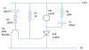
I've come up with a circuit below, but being the dunce I am with this sort of stuff, I have no idea whether I'm on the right track.

My twisted logic is that with a "flat" DC system voltage, a curret via R2 will hold the gate of the SCR open and allow it to conduct, thereby illuminating the lamp. With a "lumpy" system voltage, a small AC current will flow through the decoupling capacitor C2 and R3, causing Q1 to conduct, so shorting out the gate of the SCR and switching it off, thereby switching the light off.

Is this total bollocks, or does it have a chance of working?
If it is worth trying, are my component selections in the right ballpark? I'm guessing about a 2V minimum AC signal.

Cheers,
Cameron
 

Attachments

  • alt light circuit.JPG
    alt light circuit.JPG
    29.5 KB · Views: 2,597
Last edited:
Once an SCR is turned on, it stays on until the current passing through it goes to zero.
The DC voltage will turn the light on, but there is nothing to turn it off. .... Nothing is in the circuit to cause the DC current through the lamp to stop flowing, even though the gate bias may change.
 
Last edited:
I am not sure what you are trying to detect:

I need a simple circuit that will identify when the output from the RR exceeds the battery voltage, and switch off the alternator light when it does.

To know when the battery is charged or when the bike's alternator is charging the battery?

What you really want to detect is the current flowing into the battery. The battery is fully charged when the batt voltage reaches a certain level (actually varies with temperature) and the charging current drops below a certain level. Only then is the battery charged.

You can easily measure current flow into the battery with sense leads across the cable between the alternator and battery. You would use an amplifier to boost the voltage up, but there is a voltage drop which is proportional to current.

The battery is being charged by the alternator when the battery current is positive (flowing into the battery) and negative (flowing out) when the alt is not charging. That could easily be detected.
 
Last edited:
What I had in mind was to look at the waveform of the system voltage. When the output from the RR is lower than the battery voltage, the system voltage is the same as the battery voltage and has a smooth DC wavefom. But when the RR output exceeds the battery voltage, an AC signal is superimposed onto the battery voltage because the RR supplies rectified AC with a "lumpy" waveform.
That ripple should be pretty small. A good battery has a very low impedance and looks like a giant capacitor to filter the ripple from the alternator.
 
As far as I'm aware, motorcycles don't generally have 'alternator lights'. Probably because there's no fan-belt on a bike to break.

The charging system is most commonly a floating delta-connected 3 phase stator, feeding into a 3-ph full bridge rectifier. The rectifier connected directly to the battery. The Rotor can be a permanent magnet, or coil energised by current via slip-rings.

If the rotor is the latter, the output voltage is regulated by a controller which varies the current in the rotor, according to the voltage seen at the battery.

If the rotor is a PM, a way of dealing with it is to burn off the surplus power with a constant-voltage Shunt Regulator. On older M/Cs, this just used to be a large Zener Diode bolted to the M/C Frame and worked quite well. A M/C of this era had an Ammeter to check the health of the charging system.

If an 'alternator warning light' is desired to be added to a working charging system, one possible way is to utilise one of the 3 'phase' wires at the rectifier, since this is 'live' when the alternator is running. Another way is to have a 'battery health' or charging system gauge which is a ruggedised voltmeter with a supressed zero expanded scale.
 
Last edited:
Read my post in this thread. Adjust the trip voltage for your needs. As shown, the circuit lights a LED when a lead-acid battery is close to being totally discharged.

A 12V sealed lead-acid battery should show ~12.6V no-load, ~13.5V while being floated, and ~14.5V with the engine running. To use it as a "no-charge" indicator, you would want to set the trip point to ~ 13.2V.
 
Last edited:
Thanks guys.

Well, I was right about one thing - I don't know much about electronics.

user-88: I forgot about the "latching" effect of SCR's. Duh.

bountyhunter: I did actually make a current detector as my Mk1 design. It was an electro-mechanical device utilising a magnetic reed switch inside a heavy copper coil that carried the charging current. It actually worked quite well until it the reed switch fell to bits.

markbarker: You're quite correct. Motorcycles don't generally have alternator lghts - except Italian ones of a decade or three ago. Perhaps the Italian designers didn't have a lot of faith in their charging systems! The bike in question is a Laverda, but its electrical system is modified to include an improved electronic ignition, aditional alternator stator coil to increase output, and it now has a 3-phase shunt regulator (originally un-regulated).

Oh well, back to the drawing board. I'll go and have a look at MikeML's device.

Thanks,
Cameron
 
On a car, there are three sets of alternator diodes. One set connects the windings to negative when needed. The second set connects the windings to battery positive when needed.

The third set connects the windings to the positive of the field supply.

The alternator warning light is connected between the positive of the field supply and the battery, via the ignition switch.

The motorbike only has two sets of alternator diodes. If you fit a third set like the third set on a car altenator and a dummy load to ground fed from them, you can fit a warning light bulb just like on a car. The diodes do not need to be big. 1N5403 would be fine. The dummy load could be a bulb of about twice the power of the warning lamp, but put where it can't be seen.
 
I solved this problem a few years back on my ancient Harley (they too have unreliable charging systems)...

I used a zener diode a LED and a small resistor (in series) and a 100uF cap across the LED. The zener value was chosen so the LED starts lighting at about 13.2v, and is bright at 14v or so. It works great, if the LED is on i know the battery is charging, and it's also ramping in brightness 13.2 to 14v so it acts a little like a battery voltmeter, I can see the battery voltage come up after a ride etc. It's still going strong, over 30k miles on it now since i put the light in.
 
Status
Not open for further replies.

Latest threads

New Articles From Microcontroller Tips

Back
Top