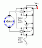
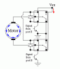
Continue to Site

Welcome to our site!

Electro Tech is an online community (with over 170,000 members) who enjoy talking about and building electronic circuits, projects and gadgets. To participate you need to register. Registration is free. Click here to register now.

  • Welcome to our site! Electro Tech is an online community (with over 170,000 members) who enjoy talking about and building electronic circuits, projects and gadgets. To participate you need to register. Registration is free. Click here to register now.

motor reversal

Status
Not open for further replies.

rancid rock

New Member
how can i make simple motor reversal,
for a 5v DC motot
plz post any circuits or advice....
 
Maybe this helps? I've tried this, no problem.
TIP 41 Transistor
1N4148 Diode
6V Relay (works at 5V)
 

Attachments

  • DC motor forward.gif
    DC motor forward.gif
    6.6 KB · Views: 180
  • DC motor reverse.gif
    DC motor reverse.gif
    6.8 KB · Views: 176
thanx mate!!!!!!!, although could u plz explain....about it,
like what needs to be done for the reversal to take effect, ty
 
...
once u turn it on, the motor will go forward. if u want to reverse it, simply give both the bases '1'. If u want to stop it, give either 10 or 01.
 
H-Bridgge

Yes, an MCU can be used.
The attached schematic is an H-bridge.

Let's get something things outlined here:

MOSFETs are transistors. They are 3 terminal devices where larger current flows through two terminals and the third terminal a small voltage signal can control the larger current. In this case, they are used as switches.

COASTING TO A STOP:
A DC motor will coast to a stop if no power is applied and no connection is made between the motor terminals. You do this by turning the all 4 MOSFETs open.

BRAKING:
But if a DC motor has it's two terminals connected together it will brake. So if you want the motor to coast to a stop, just disconnect power. If you want it to brake, disconnect power and connect the two terminals together.

In the image, this is current path is D,B, and the blue loop. You can get this by closing either Hi1/Hi2 or Lo1/Lo2. Both combinations do the same thing- short the motor terminals and make it brake.

SPINNING:
A motor's direction depends on which way current is flowing through it. You can control this by closing either Hi1/Lo2 or Hi2/Lo1. This is path C and A in the image. Each one makes the current flow through the motor in a different direction, thereby making the motor spin in different directions.

SHORTING: You never ever ever want to have either the MOSFET pairs Hi1/Lo1 or Hi2/Lo2 closed at the same time. As you can see, this would short-circuit the battery terminals. So you open and close the MOSFET "switches" in a way so that this never happens.
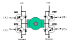
MOSFET TYPES:
There are two types of MOSFETs. NMOS and PMOS. The voltages that would turn an NMOS on or off do the opposite for a PMOS. They turn on and off in opposite ways:
SWITCH....ON......OFF
===================
PMOS........LO........HI
NMOS........HI.........LO

This has a few effects, and at this point the most important of which is that it is easier to turn a PMOS on/off if it is closer to +V on the battery. Conversely it is easier to turn on/off the NMOS if it is closer the battery GND.

NMOS conducts more efficiently than PMOS, therefore you could use NMOS for all 4 transistors. The problem is that the top two NMOS are far away from the battery GND. Higher voltages will be required to turn on the top two NMOS transistors. This "difficulty" is not trivial. The additional voltage boosting circuitry needed is often more complicated than the H-bridge itself with many many performance considerations, tradeoffs, and concessions to be had.

The other way is to use NMOS for the bottom two transistors and PMOS for the top two. NMOS transistors on the bottom will conduct more efficiently than PMOS and will be easier to switch on and off. PMOS at the top will be less efficient than NMOS but will be MUCH MUCH easier to switch on and off. The voltages supplied directly from an MCU pin are enough to do it.

And you would never use PMOS for the two bottom transistors ever. Not only would they conduct less efficiently but would be harder to switch on and off.
 

Attachments

  • brdge.gif
    brdge.gif
    9.8 KB · Views: 195
Last edited:
I was editing it a ton while you responded. You might want to read it again. Simplified the wording a lot. I was a bit simplistic in the hi and low voltages switching the MOSFETs.

MOSFETs have 3 terminals
Source- large current flows from/to here
Drain- large current flows to/from here
Gate- the voltage is applied here to control the flow

What actually determines the on/off of the transistor is the difference between the gate voltage and the source voltage (the gate voltage when referenced to source voltage). NMOSs are connected so that that the source is closer to GND and drain is closer to +V. PMOSs are connected so that source is closer to +V and drain is closer to GND (for this case and every other I can think of).

Using an NMOS in the top makes the source voltage higher than ground (unlike if the NMOS was at the bottom). Since it is the voltage difference between gate and source that determines the switching of the NMOS, a higher source means that the gate voltage must also be higher to turn on the NMOS. This is aproblem when the MCU's 5V is still referenced to ground. it just can't get high enough to turn the top NMOS on without boosting circuitry.

If the NMOS was at the bottom the source (the reference for the gate-source voltage that determines switching) would be the same as the MCU's voltage reference (0V, GND) and the MCU's 5V would be more than enough to turn the NMOS on.
 
Last edited:
can the change from forward motor motion to reverse motor motion be done without flicking a switch...for example can i have it so that when a button is pressed the motor spins forward then pause for 10 seconds then spinds back in reverse? all on its own through codeing?
 
rancid rock said:
can the change from forward motor motion to reverse motor motion be done without flicking a switch...for example can i have it so that when a button is pressed the motor spins forward then pause for 10 seconds then spinds back in reverse? all on its own through codeing?

Yes, just get hook up a button and debounce switch to a pin on the MCU. And have the MCU turn on or off the proper transistors depending on whether the button pin on the MCU is reading a 1 or 0. If you want to start doing something different after a certain amount of time, then have a timer running in the MCU. When the timer runs out the MCU can behave differently than when the button was first pressed. Perhaps you missed it (or I forgot to say it explicity) the voltage that you apply to the gate of the transistors can be done directly from the pin of an MCU, either that or you weren't aware the MCUs have timers. The pin can be 0V (low) or 5V (high). If you use the appropriate transistors in the right places, this voltage is enough to switch the transistors on and off. Since the H-bridge MOSFET transistors can be switched on and off directly from an MCU, that means you can automate the H-bridge controls to get it to behave any way you want. (Think about it, MCUs launch rockets, fly planes and missiles, control robots, etc.) All of this is done through coding. All you really have to do physically is hook up the MOSFET gates to the MCU's pins and the rest is done through coding. Oh, by the way, give a small amount of dead-time between switching transistors. They take a short amount of time to turn on and off and if you do it too quickly, the case can happen where both MOSFETs on the left or right side of the H-bridge are on which will create a short circuit (like discussed in earlier posts). Leave a small time interval (on electronics scale, not the human scale 1s is way too long) for one set of transistors to shut off before turning the next set on.

Also, if you wish to control the speed of the motor, you can "pulse" the transistors to turn them on and off at varying duty cycles to control speed. It's called PWM. Google a few articles for it. It is very simple.
 
Last edited:
thank you all sooo much, u have all helped heaps.

and thanks to u guys i have now made and designed my H-Bridge circuit!!!

thanks again....

but one last thing: whats the differances/advantages/disadvantages, between the H-Bridge and the L293D?

thanks
 
for all who want to see ur hard work and tedious explanation has paid off.

see attachment...
 

Attachments

  • hb01.jpg
    hb01.jpg
    10.5 KB · Views: 139
Ddiodes

You need to place a diode in parallel with each transistor to provide a return path for the back-EMF current from the switching an inductive load on and off, or else your transistors will die very quickly (especially if you are using BJTs instead of MOSFETs, because MOSFETs always have the diode inherently built-in due to their design. It's a byproduct though, and as such is rather slow and crummy relative to purposely designed dioes, so you still might want to use external diodes).

When you turn the motor off it will cause a current flowing in the opposite direction of what it used to be flowing. You want to place the diode such that it will allow this back-emf current to flow around the current-carrying terminals of each transistor. In other words, you want to place the diodes so that if you hook up the battery backwards to the H-bridge, it will always produce a short circuit through the diodes(don't actually do this though, I just can't think of an easier way of explaining it). If you do hook the diodes in the wrong direction this will always cause a short-circuit when you hook up the battery, so make sure you understand it before you do it.

You will need 4 diodes.
 
Last edited:
I found a picture. Hook the diodes up like shown in the picture.
 

Attachments

  • hb7.png
    hb7.png
    4.4 KB · Views: 140
argh....so this circuit i have made is wrong.....:(

ok thanks man.

hmmm, do u want me to post the parts list i used....?
 
Not wrong, just incomplete. Just add some diodes in parallel with the transistor gate and drain (for MOSFET) or collector and emitter (for BJT).

You can post the parts if you want...I won't go through them all. The transistor used and schematic is more important.
 
Status
Not open for further replies.

Latest threads

New Articles From Microcontroller Tips

Back
Top