Hello All,
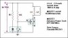
I have a question, and would be very gratefull if some one could help. I am currently working on a new type of DC electric motor, the current version of this motor uses a set of motor cycle points to turn the coils on/off, causing alot of drag and arcing across the points. :cry: Was wondering if the MOSFET circut that I have drawn up will work instead of the points. And if so could some one tell me what the R1 and R2 resistence should be. Or if the circut needs totally changed. :?:
[/img]