Electro Tech is an online community (with over 170,000 members) who enjoy talking about and building electronic circuits, projects and gadgets. To participate you need to register. Registration is free. Click here to register now.
Welcome to our site! Electro Tech is an online community (with over 170,000 members) who enjoy talking about and building electronic circuits, projects and gadgets. To participate you need to register. Registration is free. Click here to register now.
Hi hi,
IM rather confuse with MOSFET operations on how it works. If i intend to saturate a N-channel MOSFET, all i have to do is overcome its threshold voltage is it? IS the MOSFET Vgs similar to the BJT's Vbe?
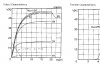
also note that saturation is a very confusing term when you are looking at mosfets vs. bjt's. they mean sort of opposite things... if you look at the V/I curves, the sort of linear region close to the y-axis is the saturation region in a BJT, but the ohmic or triode region in a mosfet. In a mosfet, the saturation region refers to the constant-current region (near-horizontal line) on the V/I curve, so it is usually a good idea to refer to it as the ACTIVE region with a MOSFET so you don't confuse yourself with BJT operation.
Is it a MUST to drive other mosfets with 10V? Since im using a PIC to drive my MOSFET( H-Bridge), im only limited to approximately 5V. When dealing with MOSFETs, what are the most important characteristic to look in the datasheet? Currently, im only experienced with BJTs. I have no idea what am i suppose to look at
look at the I/V characteristic curves for the MOSFET. they can be found in the datasheet. You aren't going to want to use the MOSFET in the active (saturation) region if you are trying to switch a large load, because it will dissipate a lot of power. You will want to use it in the ohmic region, which will give you a much lower Vds which corresponds to lower power dissipation (P=Vds*Id)
Look on the I/V curves for the device you are using. find the current level you need to drive the motor, and look at the curve for the Vgs you intend to use. if the current level falls in the ohmic region (ie- the part before the line goes semi-horizontal) then you will be OK. If not, you will either need to choose a device in which it does, or increase the voltage with which you drive the gate. the higher the Vgs you use, the lower the value of Vds for a particular current, and thus the lower the power dissipation in the MOSFET.
as long as you aren't trying to drive a huge motor, you shouldn't have too much trouble finding a mosfet that can drive a few amps in the ohmic/triode region at a gate voltage of around 4.5 or 5v as you will get from a PIC. Try looking at the IRF540. that can give you around 10 amps with a gate voltage of 4.5v, with a Vgs of only 1v, meaning only 10 watts of power, and since the device is rated for 130W of power dissipation (with proper heatsinking of course) you should be fine. If you need more than 10 amps, then you can use a separate power source and another transistor (or an optoisolator) to switch the MOSFET gate at a higher voltage from the PIC.
You aren't going to want to use the MOSFET in the active (saturation) region if you are trying to switch a large load, because it will dissipate a lot of power. You will want to use it in the ohmic region, which will give you a much lower Vds which corresponds to lower power dissipation (P=Vds*Id)
THX ALOT for the explanation.
One thing i dont understand, what is the threshold voltage purpose? From evandude explanation, all i have to do is apply the right amount of Vgs to obtain the sufficient amount of Id i require. I dont understand the purpose of the threshold.
The threshold "purpose" is such that a minimul Gate-Source voltage is needed for it to start to conduct.
This threshold is different from different type of FETS, higher voltage,higher current, different structure.
There is a depletion region (non conductive) in a FET and when you apply a voltage across the GATE and SOURCE you provide a voltage field that starts to draw charge into the depletion region.
Increase the voltage and more charge enters this region. Once a certain voltage (the threshold voltage) has been reached there is enough charge in the depletion region to form a conductive (high ohmic) path from DRAIN to SOURCE.
Increase the voltage further and more charge enters the depletion region and the thus the resistance of this region falls (decreasing the D-S imedance). You will eventually hit a saturation voltage where any more increase in voltage will not result in an increase in charge in the depletion region.
Now the device is saturated and the D-S resistance is at its minumum (for given environement/load conditions)
Id increases as (Vgs-Vt) increases assuming that Vds>or equal to (Vgs-Vt )
as styx said Vt ( threshold Voltage ) is just the turn on point of the transistor
ok i just want to get this right.
Assuming if the is Vt= 2V and Vds=12V.
If i apply a voltage of 5V to the Mosfet's gate, that would mean i have already TURNED ON my MOSFET and able to get around 15A of Id current ( referring to the IV curve). Am i right or wrong?
right. If you are running your motor at more than 5v, as i said before, you can easily add a couple transistors to operate the gates of the motor switching MOSFETs at the higher voltage, which would increase efficiency. Basically the higher the voltage on Vgs, the larger the induced channel is, and thus the more the MOSFET will look like a switch.
yes, the power supply voltage and motor windings are going to determine Vds, but if you are using a large gate voltage, then a Vds of more than a volt or two corresponds to a VERY high current, more than a reasonably-sized motor would ever draw, so Vds will remain pretty low. and of course at Vds of 1 volt, you only get 1 watt per amp of current... and with a decent Vgs you should be well below 1 volt for Vds.
Got it. My current rating is about 7A max, therefore i dont think i need a higher Vgs.
Since im going to use P-channel mosfets for my H-bridge, am i suppose to supply nagative voltage to my gate? the threshold voltage for p-channels are negative in value and that would mean i wouldnt be able to ON them without a negative signal
that's negative relative to the SOURCE, not relative to ground. with a PMOS transistor the source is at the more positive terminal (typically the positive supply terminal)
for instance, for a PMOS with the source connected to +5v, applying 0v (ground) to the gate means Vgs equals -5v.
right. If you are running your motor at more than 5v, as i said before, you can easily add a couple transistors to operate the gates of the motor switching MOSFETs at the higher voltage, which would increase efficiency. Basically the higher the voltage on Vgs, the larger the induced channel is, and thus the more the MOSFET will look like a switch.
Here is how to calculate the drain current of a MOSFET with a resistive load: When the Vds is 5 volts, the current in the load is zero, so put a point on the charactisitic graph at zero amp and 5 V. When the Vds is zero, the current in the load is 15 amps, so put a point on the graph at 15 amps and zero volts. Draw a line between those points. Where the Vgs line crosses the load line, read the drain current and Vds. I get about 3 volts Vds and 10 amps current. That represents a big power loss, you would do better with another MOSFET.
I dont understand how come the drain current is 0A when Vds is 5V. Is this done practically or am i suppose to assume that when Vds is 5V, Id=0? i also dont get the Vds=0,Id=15A part .
How come there is a big power loss? Totally loss :cry:
He's assuming a 5 volt power supply... if Vds were 5v, then there would be zero volts across a resistive load so the current would have to be zero. I don't know where he's getting the 15A from... but you would want to subsitute the current value if Vds were zero, based on the resistance of your load. for instance, say you had a 2 ohm load; if Vds were zero, then the full 5v would be across the load, so I=V/R=5v/2ohms = 2.5 amps. Since it is a resistive load you can draw a straight line from the zero Vds to the zero Id points and where that "load line" intersects the curve for the value of Vgs you are using, that is what your current will be (your operating point, or Q-point, as they call it)
P=Vds*Id. at 3 volts and 10 amps, that's 30 watts of power dissipation. using a better MOSFET you can easily get a value of Vds more like less than one volt for a drain current of 10 amps, which will cut your power dissipation immensely. The more power you are dissipating in the transistor, the less power is going to your motor.
If you can wade your way through everything we've just said, congratulations... I just realized how big of a crash course you just received in MOSFETs. keep asking questions if you need help and I'll do what I can to straighten it out for you... I know this is a lot of info to absorb when you're starting from zero.
This site uses cookies to help personalise content, tailor your experience and to keep you logged in if you register.
By continuing to use this site, you are consenting to our use of cookies.